wiring rs485 bus
Connect differential transceivers on a bus with controlled transmit direction.
Applies to: Two-wire half-duplex topology with a transceiver at every node. RS-485 itself does not define Modbus addresses or a universal connector.
Linking compatible industrial sensors or controllers along a cable.
Differential signaling supports useful noise rejection; an application protocol decides who talks and what bytes mean.
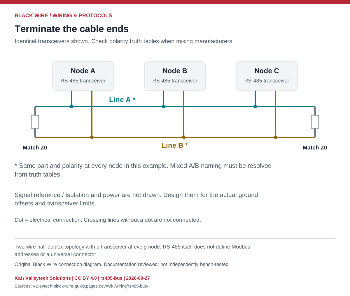
| Signal / feature | Purpose | Check |
|---|---|---|
| Differential pair | Shared data bus | A/B and +/- names can differ |
| DE | Enable the driver | Only one transmitter active at a time |
| /RE | Enable the receiver when low | Automatic-direction modules vary |
| Termination | Match cable impedance at both ends | Do not add one per node |
| Bias / failsafe | Defined idle state | Calculate for the complete loaded bus |
- Use a trunk with short stubs and the cable/transceiver guidance for the chosen rate.
- Plan the signal reference, common-mode limits and isolation before connecting separate power systems.
- Check transmit-enable timing and the protocol settings.
- GPIO cannot directly drive the differential pair.
- Termination and bias are different circuits; modules may already contain either.
This is a general interface guide; match your own hardware documentation.
Source documents inspected; independent electrical and bench review pending. Reviewed 2026-09-27.
- Texas Instruments: RS-485 Design Guide, SLLA272D — Sections on topology, termination, failsafe and grounding; checked 2026-09-27
- Analog Devices: AN-960 RS-485/RS-422 implementation — Driver enable and half-duplex bus connections; checked 2026-09-27
Original writing and diagram by Kal / Valleytech Solutions, CC BY 4.0. Manufacturer artwork and documentation retain their own rights.
CC BY 4.0 · SHA-256: 38ead3cb8203d27fc2ea439d17ee104f1ca22470e53df421fe46f9393403aa7f