PureSignal
PureSignal continuously linearises the transmit chain by sampling the RF actually leaving the PA, comparing it to what the radio's TX-DAC asked for, and computing a predistortion correction that's pushed back into the TX path. The on-air result is meaningfully lower IMD, less splatter, and cleaner third- and fifth-order products on SSB and digital modes.
The math and the WDSP calcc engine are Warren Pratt's work. OpenHPSDR Zeus ships PureSignal for:
- Hermes Lite 2 (Protocol 1) — uses the radio's internal directional coupler; no external coupler / coax run required for the everyday case. The 4-DDC PS path lights up automatically when you arm PS and key MOX/TUNE.
- ANAN G2 / G2 MkII / Saturn / Saturn-XDMA (Protocol 2) — uses an external coupler wired from the amp's forward port back to the radio's Bypass / EXT 1 RX port. Selecting "External" in the panel routes the feedback ADC there.
The same panel works on both — only the default coupler selection and a few per-board defaults differ.
PureSignal has two places you'll look at it:
- Live popover on the transport bar — at-a-glance state.
- Settings dialog → PURESIGNAL tab — full dashboard plus all the knobs.
Hover the PS button in the transport bar to see the live state without opening Settings:
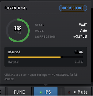
What it tells you:
-
Big number / 256 —
info[4], the WDSP feedback level, on a 0..256 scale. The sweet spot is roughly 128–181. -
STATE — current step in the
calccinner loop (more on this below). -
MODE —
AutoorSingle. - CORRECTION — the dB the predistorter is currently shaping the TX with. Zero means PS hasn't converged on a model yet.
-
CORRECTING badge (top right) — green when
info[14] = CorrectionsBeingAppliedis set, i.e. the predistortion is actually shaping your transmit signal. - Observed vs HW peak bars — the live feedback envelope peak versus the configured ADC ceiling. They should sit close together; large mismatches mean PS won't converge (see STATE vs CORRECTING).
Click PS to arm/disarm. For the full controls, open Settings and pick the PURESIGNAL tab.
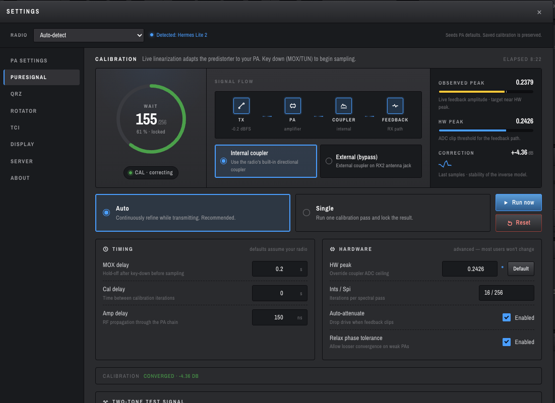
The dashboard reads top-down as a live calibration cockpit. The top-right ELAPSED chip is the time since you armed PS this session.
-
Big ring + number — the same
info[4]/256feedback level as the popover, with a green progress arc. The label inside the ring is the current STATE (WAIT,COLLECT,CALC,DELAY, etc). -
xx % · locked— the fraction ofcalcc's amplitude bins that have filled enough samples to be usable. Reaches 100 % when the engine has a complete, stable model. - CAL · correcting chip — same as the green CORRECTING badge in the popover.
The chip strip mirrors what's actually happening on the wire:
TX (TX-DAC, dBFS) → PA (amplifier) → COUPLER (internal/external) → FEEDBACK (RX path)
The TX -0.2 dBFS reading is your TX-DAC peak — useful when checking that drive isn't being clipped by the predistorter. COUPLER reflects whichever radio you're connected to (HL2 defaults to internal).
This is the most important pairing on the page:
- OBSERVED PEAK — live feedback envelope amplitude (the actual RF coming back through the coupler).
- HW PEAK — the configured ADC clip threshold for the feedback path.
calcc divides amplitudes into 16 bins between 0 and HW peak. To complete a calibration pass it needs every bin to fill — that means OBSERVED must reach close to HW PEAK. If observed is way below HW peak, the top bin never fills and calcc loops in COLLECT forever, never converging.
OpenHPSDR Zeus auto-tunes HW peak to match observed peak whenever PS is armed and TX is stable; you generally won't have to touch it. The blue dot next to the HW peak field in HARDWARE means the value differs from the per-board default — totally normal once auto-cal has run.
The CORRECTION ±X.XX dB number is the magnitude of the inverse model calcc is currently applying. Watch for it to settle once converged — wandering by tenths is fine, swinging by whole dB means something is unstable (typically HW peak is wrong or the amp is being asked to do something it can't linearise).
- Internal coupler — HL2 uses its built-in directional coupler. The default on HL2.
- External (bypass) — the radio routes the feedback ADC to the Bypass / EXT 1 RX port, where you've wired your amp's forward-coupler tap. The default on Protocol-2 boards.
The selector stays visible on every board (HL2 has an internal coupler but you can still wire an external one if you want to PureSignal an external linear). Don't hide it.
-
Auto (default) —
calcccontinuously refines the correction while you transmit. This is what you want for normal operating; the engine retrains on every key-down without losing the previous model. - Single — run one calibration pass and lock the resulting correction. Useful when you want a known-stable correction on the air for a defined window.
The Run now button forces an immediate calibration cycle (handy when you've changed bands or amp configuration). Reset clears the current model so the next key-down starts from scratch.
-
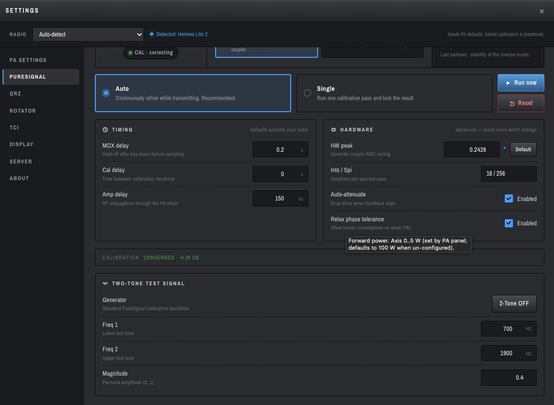
MOX delay (default
0.2 s) — settle time after key-down before the engine starts sampling. Keeps PA inrush transients out of the model fit. -
Cal delay (default
0 s) — gap between successive calibration iterations.0means back-to-back cycles, which is what most setups want. -
Amp delay (default
150 ns) — RF propagation time through the PA chain (input to coupler tap). Most LDMOS bricks land in 100–250 ns; only worth measuring if you suspect time-alignment problems.
- HW peak — see Observed vs HW peak above. Default restores the per-board factory value.
-
Ints / Spi —
calcc's spectral pass parameters asints/spi(16/256 by default). Iterations × samples-per-iteration; only change if you know what you're doing. - Auto-attenuate — when on, the engine continuously trims the radio's TX step attenuator to keep the feedback envelope inside the WDSP target window. Default ON. Turn off only if you need manual control of the step attenuator.
-
Relax phase tolerance — relaxes
calcc's polynomial-tolerance check (analogous to Thetis's "Relax Tolerance"). Useful on weaker / less-linear PAs. Default ON on HL2 since the HL2's internal PA is small.
CALIBRATION CONVERGED · -X.XX DB along the bottom is your "we're done settling" indicator — once you see it, the correction has stabilised at the listed dB.
A standard two-tone excitation generator for benchmarking your PA's linearity (with and without PS engaged):
-
Generator —
2-Tone OFF / ON. Drives the TX with two pure sines at the configured frequencies and amplitude. - Freq 1 / Freq 2 — the two test tones (defaults 700 Hz / 1900 Hz, which is the standard two-tone IMD spacing).
- Magnitude — per-tone amplitude (0..1).
Useful for visually confirming PS is doing something: arm 2-Tone, key TUNE, watch IMD shoulder products on a KiwiSDR or external receiver — they should drop several dB when PS converges versus when it's disarmed.
This is the single most common source of confusion, so it deserves its own section.
calcc is a state machine. While you're transmitting in Auto mode it cycles continuously through:
WAIT → MOXDELAY → SETUP → COLLECT → MOXCHECK → CALC → DELAY → COLLECT → ...
The STATE label in the popover and the calibration ring shows you which step it's currently in. There is no CORRECTING step — calcc doesn't have one. Whatever step you happen to catch, that's what STATE will show.
The CORRECTING badge is a separate orthogonal flag (info[14] = CorrectionsBeingApplied). It turns on as soon as calcc has computed a valid correction it can push to the TX path, and stays on across all loop steps. That's the indicator you want to look at to know "PS is currently linearising my signal."
So a snapshot showing STATE = COLLECT and CORRECTING green at the same time is correct and healthy:
- STATE says "right now I'm filling envelope bins for the next refinement pass."
- CORRECTING says "and the previous pass's correction is being applied to TX."
A snapshot showing STATE = WAIT and CORRECTING green means calcc finished a cycle, has a model in place, and is waiting for the next key-down or sample window to refine again.
You'd only worry if CORRECTING never turns on, or if CORRECTION stays at 0 dB — those mean the engine couldn't find a usable model.
- Wire it up (P2 / external coupler only): coupler forward port → coax → radio Bypass / EXT 1 port. Power the amp. (HL2 with internal coupler: skip this — you're already wired.)
- Connect to the radio.
- Tune to a band where you actually operate.
-
Open Settings → PURESIGNAL. Confirm:
- PS = on (or hit the PS button in the transport bar).
-
Mode =
Auto. -
Coupler =
Internal(HL2) orExternal(P2 with external linear). - Auto-attenuate = on.
-
Key MOX with mic for ~10 seconds (or use 2-Tone with TUNE). Speak normally —
calccneeds real envelope content; a constant carrier doesn't carry the modulation statistics it fits to.
You should see, in order:
- The Observed bar lifts off zero and approaches HW peak.
- The ring fills past 50 % and the STATE label cycles WAIT → COLLECT → CALC.
- CORRECTING badge turns green; CORRECTION reads a non-zero dB value.
- Footer flips to
CALIBRATION CONVERGED · -X.XX DB.
On an external receiver (KiwiSDR, second rig) you should hear distinctly cleaner IMD product levels.
- Uses the internal directional coupler by default. You don't need to wire an external coupler.
- The HL2's PA is small (~5 W rated), so
Relax phase tolerancedefaults ON. - HW peak factory default is 0.2400, but auto-cal almost always converges to something slightly different (commonly 0.18–0.25 depending on band and drive). The blue dot next to HW peak is informational, not an error.
- Brief mismatch on MOX edges (1–3 ms while the wire-side Config frame propagates) is tolerated; pscc resets cleanly.
- Use an external coupler wired to the Bypass / EXT 1 port. Switch the Coupler selector to External.
- HW peak factory default is 0.6121 (per pihpsdr
transmitter.c). - AutoAttenuate typically settles in 18–25 dB of step attenuation on a 1 kW external linear; YMMV.
- HW peak factory default is 0.2899.
- Otherwise the same workflow as G2.
The feedback path isn't carrying RF. Check:
- HL2: Is PS in the Internal coupler position? The selector is shared between boards.
- P2 / external: Is the coupler-to-Bypass coax actually connected to the right port?
- Anything: tune into a dummy load and key TUNE briefly. If Observed still doesn't move, look at the wiring before suspecting software.
calcc divides 0..HW peak into 16 bins; the top bin needs to fill before LCOLLECT → LCALC. If Observed is well below HW peak the top bin never fills and the engine loops in COLLECT forever.
OpenHPSDR Zeus auto-tunes HW peak toward Observed automatically once PS is armed and TX is stable. If you've manually overridden HW peak, click Default in HARDWARE to reset, or just lower HW peak to ~Observed * 1.02 and let the engine take over.
You're not actually keying. Check the transport bar — MOX or TUNE must be on for calcc to leave WAIT.
Your coupler is delivering more signal than 31 dB of step attenuation can knock down. Either add an external 10–20 dB pad inline, or use a coupler with more isolation (40 dB minimum is reasonable).
Confirm the feedback path is actually the right RF: tune into a dummy load, key MOX briefly, watch Observed move. Then key the antenna and confirm CORRECTION dB stays in the same ballpark — drastic differences mean an antenna-system issue is dominating, not a PS issue.
Re-arm PS. PS state isn't persisted across reconnects (deliberately — see PR #229) so you have to click PS back on after a fresh connection.
- Warren Pratt's PureSignal paper — PureSignal Adaptive Pre-Distortion (Public), Friedrichshafen 2014. The original conceptual document.
-
Thetis source —
Source/Console/PSForm.cs(UI +timer2codeAutoAttenuate),Source/Console/cmaster.cs(wire-side PS),Source/Console/clsHardwareSpecific.cs(per-board defaults). - mi0bot Thetis fork — the authoritative reference for HL2 PureSignal behaviour.
-
pihpsdr source —
src/transmitter.c(engine arm +ps_setpkper board),src/new_protocol.c(wire format). -
WDSP source —
native/wdsp/calcc.cis the canonical state machine.
-
PureSignal Feedback Calibration — bench procedure for setting
HW Peakon chains that don't match the per-board defaults (external taps, amp directional couplers, inline pads). - TX Controls — MOX / TUNE / drive controls that pair with PureSignal.
- Meters — TX stage meters where PS feedback shows.
- PA Settings — power calibration that the PS engine relies on.
-
Bandwidth and Filters — TX filter, which determines the bandwidth
calccis fitting to.