Repository navigation
make_mesh_from_points
Warning
This function is experimental and may break easily. It currently only works with the Princeton nokura bucket and the "brain_and_nerve_cord" datastack. Manual alpha value setting and autogrow shutoff will likely be removed in future versions once the autotightener has been more thoroughly vetted.
This function takes a shortened neuroglancer link with one or more point annotation layers and generates a legacy-format, single-resolution, unsharded neuroglancer mesh volume from it, saves that volume to a bucket, and returns a shortened neuroglancer link containing both the original point annotation layer and a segmentation layer with the resultant mesh.
Arguments:
-
datastack(string, mandatory)- the name of the CAVE-hosted, tracer-config-supported datastack the mesh will be generated in
-
share_url(string, mandatory)- the shortened neuroglancer link containing the point annotation layer to be meshed
-
bucket_path(string, mandatory)- the address of the bucket location where you want the mesh volume to be stored (currently only supports the Princeton nokura server)
- the last folder name in the bucket path will be the top-level folder of the volume
- e.g. if your bucket path is
"my://bucket/path/vol_01"thevol_01folder will be the neuroglancer volume - this will create new folders where none yet exist if they're included the path
-
alphas(list of floats or integers, optional, default=None)- the starting alpha shape radius values you want to use for each submesh made from a point annotation layer
- length of this list must match number of point annotation layers in share url
- passing an alpha value of None for one of the list items will attempt to generate one automatically
- the default value of None for the whole list sets all the individual list item values to None
-
auto_grow(boolean, optional, default=True)- default value of True allows for iterative increase of alpha until a watertight mesh is produced
- if set to False, will only try first alpha value for each submesh, which is prone to failure
-
save_objs(boolean, optional, default=False)- if True, will save an OBJ file for each of the submeshes and the final mesh
- saves in the location specified by the
obj_pathargument
-
obj_path(string, optional, default=None)- the absolute path to the folder where you want OBJ files produced by setting
save_objsto True to be saved - the default value of None attempts to find your machine's default
Downloadsfolder
- the absolute path to the folder where you want OBJ files produced by setting
-
print_alphas(boolean, optional, default=False)- if set to True, will print the final alpha values for each submesh
- can be useful for troubleshooting
-
nokura(boolean, optional, default=True)- !!!this option currently doesn't do anything, but is in place for future updates to allow non-nokura bucket use!!!
- whether or not the bucket being used is the Princeton nokura server
- by default, modifies passed bucket address to public-facing host format for nokura
- if using non-nokura bucket, must be set to False
-
smooth_mesh(integer, optional, default=0)- how many iterations of smoothing to apply to the final mesh
- uses
trimesh.smoothing.filter_taubin() - occurs before decimation
- passing a float instead of an integer will round down
-
smooth_submesh(integer, optional, default=0)- how many iterations of smoothing to apply to the submeshes
- uses
trimesh.smoothing.filter_taubin() - occurs before decimation
- passing a float instead of an integer will round down
-
decimate_mesh(float, optional, default=0.0)- if set to value between 0.0 and 1.0, will attempt to reduce the number of final mesh faces by this proportion
- e.g. a value of 0.3 would try to reduce a 100-face mesh to 30 faces
- occurs after smoothing
-
decimate_submesh(float, optional, default=0.0)- if set to value between 0.0 and 1.0, will attempt to reduce the number of faces by this proportion for each submesh
- e.g. a value of 0.3 would try to reduce a 100-face mesh to 30 faces
- occurs after smoothing
-
autotighten(boolean, optional, default=True)- whether or not to automatically tighten each submesh as much as possible
- works by iteratively trying an alpha value of the average of the last failed and last successful alphas
- stops when difference between last failed and last successful is less than 1
Returns:
-
link(string)- the shortened link to the neuroglancer state containing the final mesh
- this includes all the annotation layers that created it for inspecting accuracy
- mesh layer name includes final alpha values used for each submesh
- In addition to returning the link, this function also saves a neuroglancer legacy-format volume containing a single-resolution mesh in the specified bucket location. This is required to generate the link, since it serves as the host site for the mesh layer. It also optionally saves OBJ files for each submesh and the final mesh if the
save_objsargument is set toTrue.
Before diving into the examples for this function, it's a good idea to understand how it works. If all we wanted was a convex hull, this would be simple to generate. Convex hulls are created by connecting the outermost points in a cloud and ignoring everything inside. This is fine for many purposes, but often you'll need to be able to make more detailed shapes that include concave regions. Doing this automatically, however, becomes complicated very quickly. Take the diagram below for example:
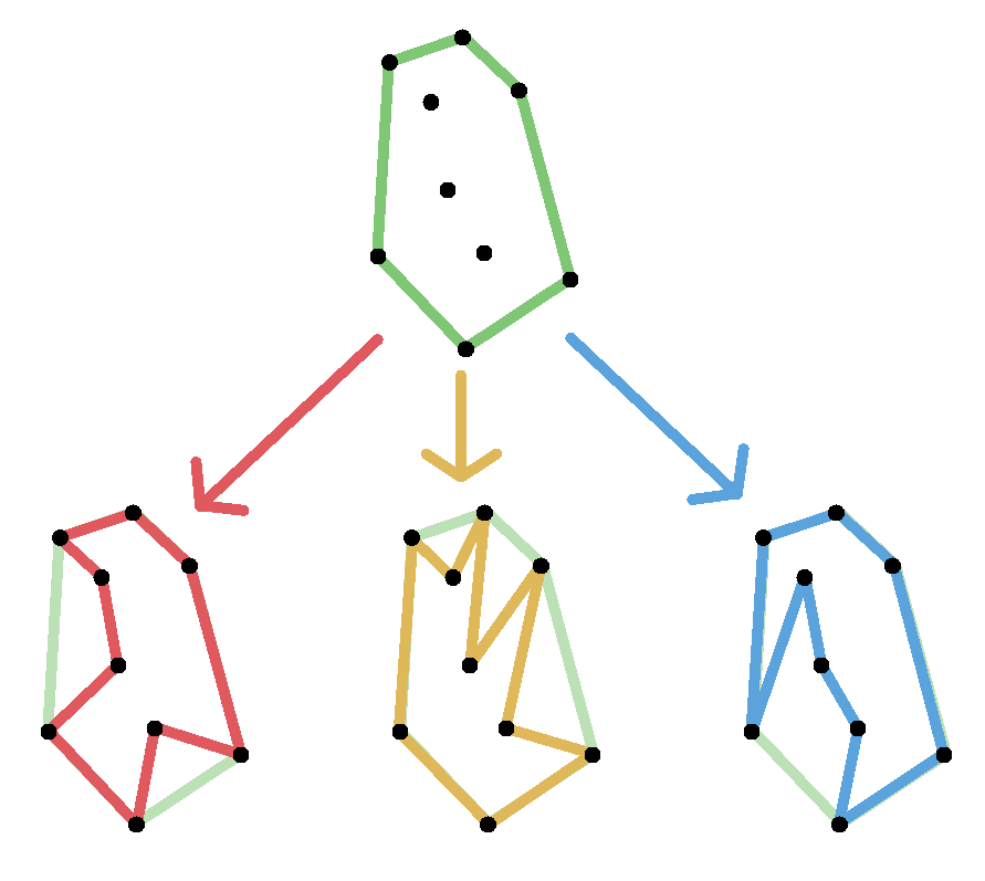
If we start with the black point cloud, we can easily generate the green convex hull at the top. However, if we want to include concavities, the computer doesn't know exactly which of the many possible "legitimate" configurations of point connections to use. All three of the shapes on the bottom row are legitimate possible ways of connecting the point cloud into a watertight concave shape. The problem is even more difficult when you add a third spatial dimension.
To solve this issue, we can use a process called Delaunay Triangulation, or more specifically, a modified version of it that produces a structure called an alpha shape. Without going into the math too much, Delaunay Triangulation connects points into triangles in a way so that each triangle's circumcircle (the circle on which all three points that make up the triangle lie) doesn't have any points inside it. The process works very similarly in 3D except that instead of making triangles by fitting 3 points to a circle, it makes tetrahedrons by fitting 4 points to a sphere. See the diagram below for a 2D visualization of the result (ignore the red dots, those are just the centerpoints of the circles):
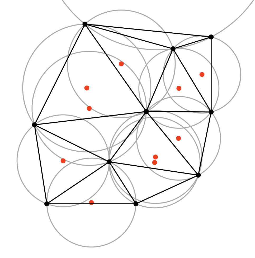
The above image was derived from public domain work on Wikipedia by user Nü.

The alpha shape technique then takes this result and removes all the triangles too large to fit into a circle of a specified size. The radius of this circle is called the "alpha" value. A smaller alpha value will produce a more detailed final result, but risks breaking apart points in a way that creates holes in the output. See the example below for a visualization*:
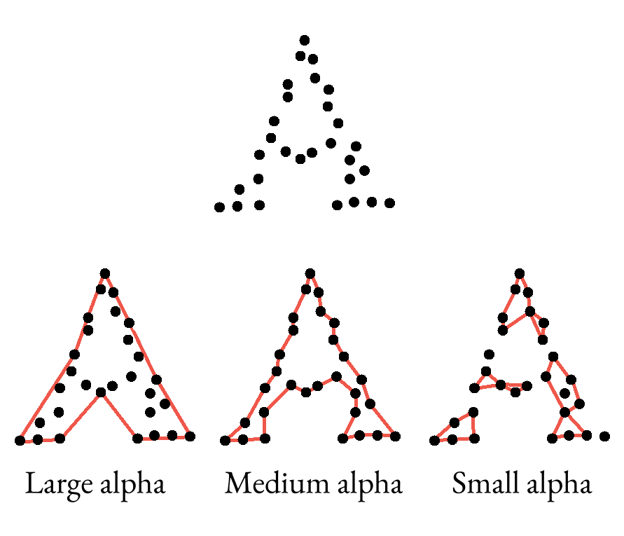
Note
This is only showing what the exterior hull of the final shape would look like, the actual triangles aren't drawn. This is also a hand-drawn example, so there may be some slight spatial inaccuracies since it's not generated from actual data.
Trying different alpha values for the same point cloud is therefore often necessary to hone in on a good final result that's as tight to the original points as possible without creating gaps in the mesh. This function starts at an alpha value equal to 1.5 times the median distance between each point and its nearest neighboring point by default, then tries repeatedly incrementing the alpha value up by 50% with each pass until it hits a mesh that's "watertight" (one that doesn't have any holes in it).
If autotighten is set to True (which it is by default) it will then step backwards, iteratively trying alpha values halfway between the last successful and last failed values until these two values are less than 1 apart.
It does this for each of the point annotation layers in the initial neuroglancer link, then fuses all the resulting meshes together using a trimesh boolean manifold union operation.
In order to see what the initial, last failed, and final alpha values were for each submesh, you can set the print_alphas argument to True.
Prior to the creation of the autotightener, manual alpha value passing was often necessary. This option has been left in for now, but will likely be removed in the future once the autotightener has been more thoroughly vetted for bugs and is therefore not recommended. If you do want to manually set the alpha values for some reason, you can set the auto_grow and autotighten arguments to False and manually pass a list of alpha values for each submesh (in the order their parent annotation layers appear in the neuroglancer link) with the alpha argument.
The results of the default mesh generation can look a little jagged sometimes. While this may be more accurate to the geometry of the original point cloud, it's often not necessary or desired. To soften this effect, smoothing can be used with the smooth_mesh and smooth_submesh arguments. The integer you feed in is the number of smoothing passes the function will put the mesh through. Generally it's not recommended to do more than 1 or maybe 2, as higher numbers may produce distorted results.
The smoothing in this function uses trimesh's baked-in smoothing.filter_taubin() method, which uses laplacian smoothing with taubin filtering - a process I won't pretend to understand, but which has so far produced good results.
While the automatic mesh generation is often fairly good, it can sometimes produce results that contain more triangles that are really necessary to achieve the desired shape. Since more triangles require more computational power to both render and perform analysis on (e.g. with the calc_seg_mesh_intersect function), it's often useful to run your mesh through a decimation process. This reduces the total number of triangles as close to the requested number as possible without creating holes in the mesh.
Decimation happens after smoothing in each step (i.e. submesh decimation happens after submesh smoothing and final mesh decimation happens after final mesh smoothing). This order was chosen based on trial and error during testing, which consistently produced better results.
The decimation in this function uses trimesh's baked-in simplify_quadric_decimation method, which is itself based on open3D's simplify_quadric_decimation method, which ultimately derives from a mathematical technique called Quadric Error Metric Decimation.
This function also offers the optional ability to save all the individual layer meshes, as well as the final combined mesh, as OBJ files by setting the save_objs argument to True and optionally passing the absolute file path to the directory where you want them saved as a string with the obj_path argument (otherwise it tries to put them in your default Downloads folder if one exists). These OBJ files are often useful for manual manipulation of the meshes in a program like Blender.
Below are some examples showcasing how to use the different options and what kind of results they produce.
Let's say we wanted to make a rough approximation of the space taken up by the right DNp01 neuron from the brain_and_nerve_cord datastack. In neuroglancer, you could create a single annotation layer and drop a number of points all over the surface of the neuron, like this. Then you could feed that link into the function along with the name of the datastack and the location on a bucket you have write access for where you want the mesh volume to be stored (this bucket path will replace the dummy string in the example below).
INPUT:
import tracertools as tt

link = tt.make_mesh_from_points(
    datastack = "brain_and_nerve_cord",
    share_url = "https://spelunker.cave-explorer.org/#!middleauth+https://global.daf-apis.com/nglstate/api/v1/5339754808213504",
    bucket_path = "bucket://location/of/volume/folder",
)

print(link)
If everything worked correctly, you should end up with a neuroglancer url as the output. This link below has been adjusted slightly to frame the spot we're interested in. By default it will be zoomed way out and set to a dorsal camera angle.
OUTPUT:
https://spelunker.cave-explorer.org/#!middleauth+https://global.daf-apis.com/nglstate/api/v1/5084604659138560
As you can see, the result of the basic method is somewhat jagged and rough and contains a lot of "webbing" - undesired connections between the branches. While the triangulation process used in this function can trim some of this, it becomes more difficult the closer the branches are, and the shallower the angle between them.
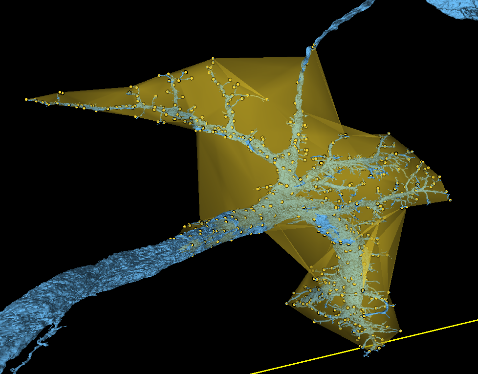
Yellow annotation points show the original point cloud for comparison.
To fix this, we can split our original annotation layer into multiple separate layers, each one covering one branch of the arbor like this. Make sure these point clouds overlap with those from at least one other layer, so the mesher can join all the submeshes properly. Swapping this url out for the one in the original code gives us a mesh that's much tighter (link adjusted to show original mesh in yellow, new in red).
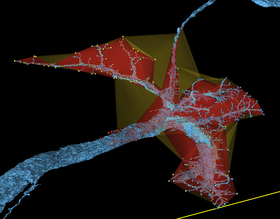
The original mesh is shown here in yellow, new in red for comparison.
Despite tightening the mesh up, the above approach looks rather jagged. This is where smoothing can be helpful. The following code adds a single smoothing pass to the final mesh. To smooth each submesh before merging them, you can instead use the smooth_submesh argument in the same way.
INPUT:
import tracertools as tt

link = tt.make_mesh_from_points(
    datastack = "brain_and_nerve_cord",
    share_url = "https://spelunker.cave-explorer.org/#!middleauth+https://global.daf-apis.com/nglstate/api/v1/6485078000009216",
    bucket_path = "bucket://location/of/volume/folder",
    smooth_mesh = 1,
)

print(link)
This time the results are fairly similar, but you can see in this link where the smoothed mesh (in red) has grown or shrunk various parts of the previous mesh (in yellow) in order to smooth the jagged edges.
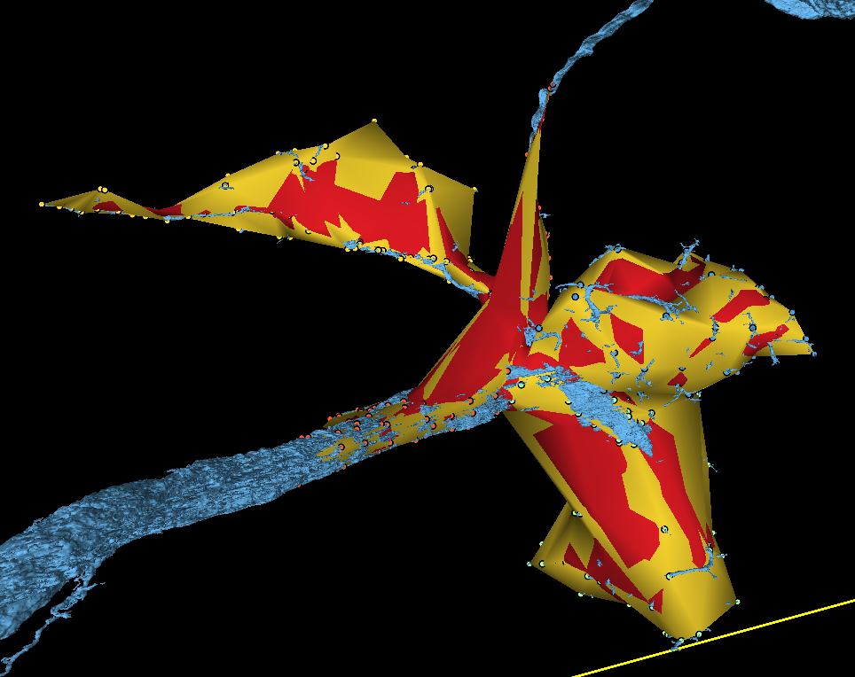
Spots where the smoothed mesh grew are red, spots where it shrank are yellow.
As you can see in this comparison link, smoothing the submeshes produces a very similar result to smoothing the final mesh. The effects are usually most noticeable around the joints between submeshes, as shown in the image below where the submesh smoothing is in red and the final mesh smoothing in yellow.
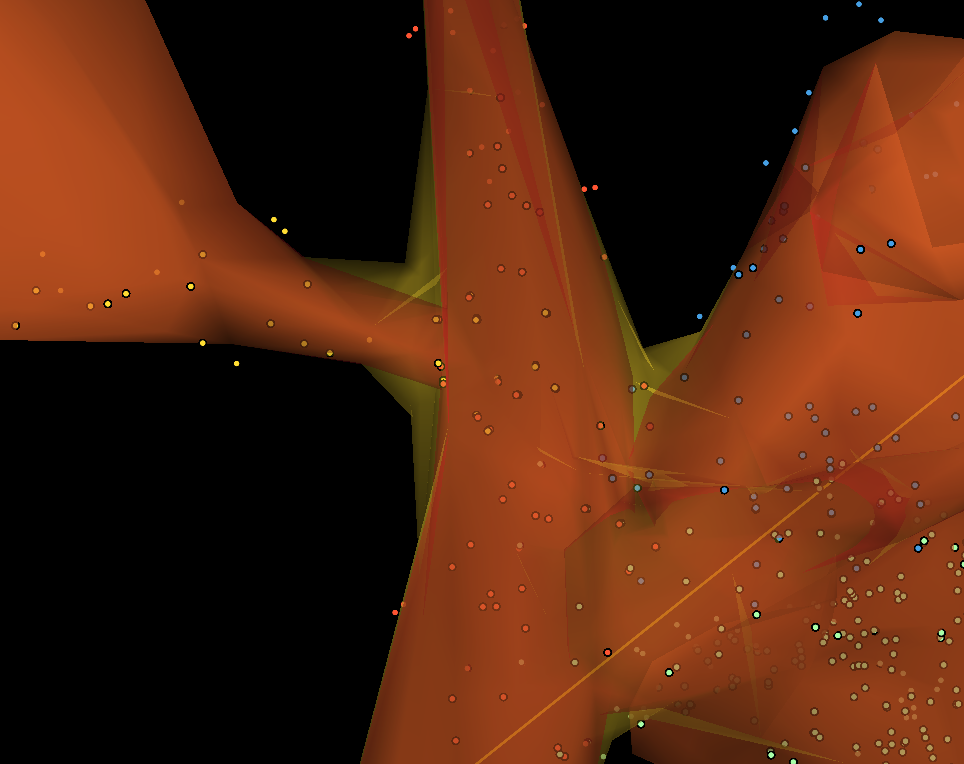
Submesh smoothing (red) is tighter at joints than final mesh smoothing (yellow).
Decimation can help reduce the redundant vertices leftover from the initial mesh generation, submesh joining, and smoothing. To use it, pass a value between 0.0 and 1.0 with the decimate_meh or decimate_submesh arguments. This will attempt to reduce the total number of faces in the mesh to whatever proportion you chose. For example, passing a decimation value of 0.3 for a mesh with 100 faces would try to reduce it to 30 faces (100 initial faces * 0.3 decimation value = 30 final faces). If the number of faces is too low to produce a watertight mesh, the function will default to the lowest number that succeeds. For this reason, it's often useful to try a low value first - like 0.1 - to see what the maximum reduction looks like, then gradually raise the decimation value until you're happy with the result. If we use out earlier example, the code looks like this:
INPUT:
import tracertools as tt

link = tt.make_mesh_from_points(
    datastack = "brain_and_nerve_cord",
    share_url = "https://spelunker.cave-explorer.org/#!middleauth+https://global.daf-apis.com/nglstate/api/v1/6485078000009216",
    bucket_path = "bucket://location/of/volume/folder",
    decimate_mesh = 0.1,
)

print(link)
The output will include a link, but also a message that lets you know how many faces the final product has. For our code above, it looks like this:
Mesh decimation successful. 1094 faces reduced to 802 faces.
As you can see in this link, despite a 26% reduction in the total number of faces for the decimated mesh (red), the visual appearance is nearly identical to the original (in yellow). Decimating the submeshes instead can produce a more noticeable difference, particularly around the joints like with smoothing.
Note
Currently a bug exists where extreme decimation of submeshes can pull their boundaries too far apart to join, resulting ins a "Not all meshes are volumes!" ValueError. For this reason, final mesh decimation is recommended until a failsafe can be implemented.
You may have noticed throughout these examples that the mesh was jagged, inconsistent, and somewhat inaccurate. This is largely because the original points were placed very haphazardly. When laying down points to create your meshes, try as much as possible to break the mesh down into nearly-convex sub-shapes with minimal bending or concavity. Likewise, try to place many points spread evenly apart. For neuritees, which often take the form of long, arcing cylinders, try placing the points in "rings" around the path, making a new sub-shape whenever the path bends more than a little bit. This will help preserve as much of the original curvature as possible.
Also, it's better to cap long, thin structures like these off at the end with a final "ring" of 3 points in a triangle about half the size of the previous ring, rather than leaving the end as a blunt circle that can cause concavity issues or a single point that can be removed entirely during decimation or smoothing operations.
Speaking of decimation and smoothing: these processes usually shrink the overall boundaries by a bit, so it's a good habit to place your points a bit outside the area you want to enclose with the mesh, creating some "padding" for the smoothing and decimation to chew through. This will also help create clean transitions at submesh joints.
If you're attempting to write to a bucket on the PNI network while using a PNI connection (like eduroam), you have to make sure you've turned on the University's VPN (GlobalProtect). Otherwise this function will break when it tries to upload the mesh volume with the error ValueError: IntervalTree: Null Interval objects not allowed in IntervalTree.