Class Collaboration Diagram
A class collaboration diagram gives us a bird's-eye view of communication pathways inside our Vehicle Guidance domain.
The following participants are shown:
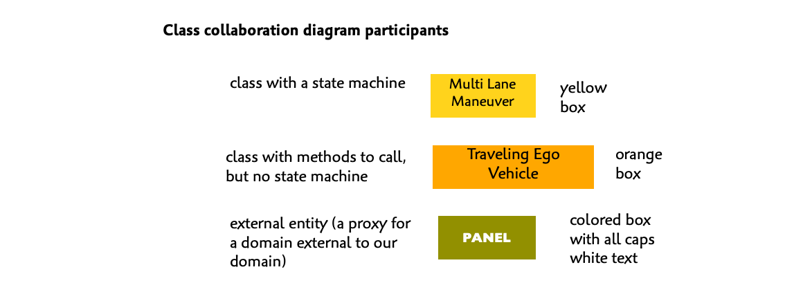
Internally, we see interactions among our state machines as well as invocations of methods on some of our classes. For example, we see that the Driving Lane Change state machine may report success to the Multi Lane Maneuver state machine. Whether it does or not for a given scenario is something we would see on a sequence diagram. The class collaboration diagram is true regardless of scenario so it just shows that the success report is possible.
We also see run-time dependencies on supporting domains represented as interactions with external entities. For example, the PANEL external entity serves as a proxy for the instrument panel / driving cockpit. We see that the Driving Lane Change state machine depends on it for activation and detection of the turn indication status.
We have the following kinds of interactions in our models:
- Signal/event exchanged between two state machine instances within the same domain (asynchronous)
- Class method invocation on an instance of a class (synchronous)
- External entity operation (asynchronous or synchronous)
- Domain operation (synchronous)
- Signal/event emitted by a domain operation and upon invocation and directed to a state machine (asynchronous)
All interactions are either asynchronous or synchronous. Asynchronous interactions are events (signals) generated by state machine actions or external enti. Events are exchanged only between state machines and only within the same domain. Rules for how signals are processed in Executable UML can be found in this video. Synchronous interactions are more like function calls in a programming language. In our models these are class method invocations or