Sketching and Dimensions
Sketches are the foundation for most editable CAD work in Cindr3D. A clean sketch makes later features easier to edit, suppress, configure, and export.
Every sketch lives on a plane. Start on an origin plane, a planar face, or a construction plane.
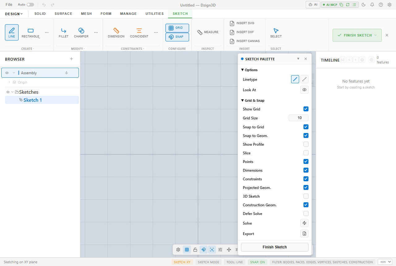
Basic flow:
- Click Sketch in the Create ribbon, or press
S. - Pick a plane or planar face.
- Draw 2D geometry.
- Add constraints and dimensions.
- Finish the sketch.
The viewport aligns to the sketch plane, the ribbon switches to sketch tools, and the sketch origin/axes become visible.
The Sketch ribbon includes common 2D primitives and editing tools.

Common tools:
- Line and polyline.
- 3-point arc and center-radius arc.
- Rectangle and center rectangle.
- Circle, 2-point circle, and 3-point circle.
- Ellipse.
- Polygon.
- Straight slot, center-point slot, and arc slot.
- Spline and fit-point spline.
- Conic curves.
- Text profiles for embossing or engraving.
Use editing tools to clean the sketch before turning it into a feature:
- Sketch Fillet: insert a tangent arc at a corner.
- Trim: remove segments to the nearest intersection.
- Extend: lengthen a segment to the next intersection.
- Offset: create parallel curves.
- Mirror: reflect selected entities across a line.
- Move/Copy: translate selected geometry.
- Scale and Rotate: transform selected entities around a pivot.
- Project: reference existing model edges or silhouettes.
Constraints define relationships between entities. They are usually better than eyeballing geometry.
Important constraints:
- Horizontal and Vertical.
- Parallel and Perpendicular.
- Tangent.
- Coincident.
- Equal.
- Concentric.
- Symmetric.
- Fix.
- Collinear.
- Midpoint.
- Smooth/G2.
Over-constrained sketches turn red. Remove the conflicting constraint or dimension before building downstream features.
Press D to place a driving dimension.
Dimension types:
- Linear: horizontal or vertical extent.
- Aligned: true point-to-point distance.
- Radial: arc radius.
- Diameter: circle or arc diameter.
- Angular: angle between two lines.
Double-click a dimension to edit it. Expressions such as 50/2 can be used where supported.
The Sketch Palette groups display and behavior toggles.

Useful toggles:
- Construction: convert selected geometry to reference lines.
- Look At: align the viewport to the sketch plane.
- Profile shading: highlight closed regions.
- Show Constraints: display constraint icons.
- Grid Snap: snap cursor to the sketch grid.
- Point Snap: snap to points, intersections, midpoints, and centers.
Finish Sketch returns to the Design ribbon. Closed profiles become available for Extrude, Revolve, Loft, and related features. Open profiles can drive Sweep, Pipe, or Rib features.

To re-edit a sketch, double-click it in the component tree or timeline, or right-click and choose Edit Sketch.