P3X VPS Module board
Function
Variants
Parts
Programming
External interfaces
Service interfaces
Board view
Schematics
The Visual Positioning System board contains a camera and a sonar. It is able to stabilize position of the drone indoors and in situations where GPS isn't available. It only works at low altitudes.
The known variants have only minor differences.
| Marking | Overview |
|---|---|
| P00903.T2 | |
| P00903.T3 |
| Marking | Amt. | Pkg. | Function | Specification |
|---|---|---|---|---|
| KJE C6 | 2 | |||
| LFW 55 | 2 | |||
| BR4 | 4 | Philips BSR33 Si PNP transistor; Uce 80V, Ic 1A | ||
| C65 | 1 | |||
| 3PEAK TP2274 KAEh | 1 | TP2274 - 36V, 7MHz Bandwidth, RRO Quad Op‐amps | description | |
| M058ZDN 524AD 2521B033 | 1 | Nuvoton M051 Series MCU with ARM Cortex-M0 core | description | |
| ARM2 STM32F 407IGHb 78AEF VQ PHI | 1 | High-performance foundation line, ARM Cortex-M4 core with DSP and FPU, 1 Mbyte Flash, 168 MHz CPU, ART Accelerator, Ethernet, FSMC | description | |
| T120 MfNA | 1 | Quartz oscillator, 12MHz | ||
| INVENSENSE MPU-6050 D4F971L81 EL T530 E | 1 | TDK Six-Axis (Gyro + Accelerometer) MEMS MotionTracking Devices | description | |
| CYY TYF 5327 | 1 | |||
| W1A 55 | 1 | PMST3904 NPN switching transistor | description |
| Chips | Firmware | Description |
|---|---|---|
| unknown | m1700 | Camera positioning measurement firmware. |
| unknown | m1701 | Sonar altitude measurement firmware. |
Connectors on the board are:
| Marking | Overview |
|---|---|
| 4-pin ribbon cable con. | Ribbon cable connector |
The following service pads exist on this board:
| Marking | Overview |
|---|---|
| 3V3 | Power supply 3.3V. |
| GND | |
| SD_D0 | |
| SD_D1 | |
| SD_D2 | |
| SD_D3 | |
| VCC_TX30 | |
| GND | |
| ULTRA_RXD | |
| ULTRA_TXD | |
| 5V | Input power supply 5V. |
| GND | |
| 3V3 | |
| GND | |
| U6_TXD | UART interface 6, transmit. |
| U6_RXD | UART interface 6, receive. |
| DEBUG_TXD | |
| COMP_NEG | |
| POT_R6 | |
| KA | |
| TICE_CLK | |
| TICE_DAT | |
| VCC_AMP | |
| GND | |
| U2_TX | UART interface 2, transmit. |
| U2_RX | UART interface 2, receive. |
| ART3_TX | |
| ART3_RX | |
| GND | |
| SWPIO | |
| SWLK | |
| PWM | |
| U4_RX | UART interface 4, receive. |
| U4_TX | UART interface 4, transmit. |
| VAA_PIX | |
| 1V5 | Power supply 1.5V. |
Top of a T2 board:

Bottom of the T2 board:

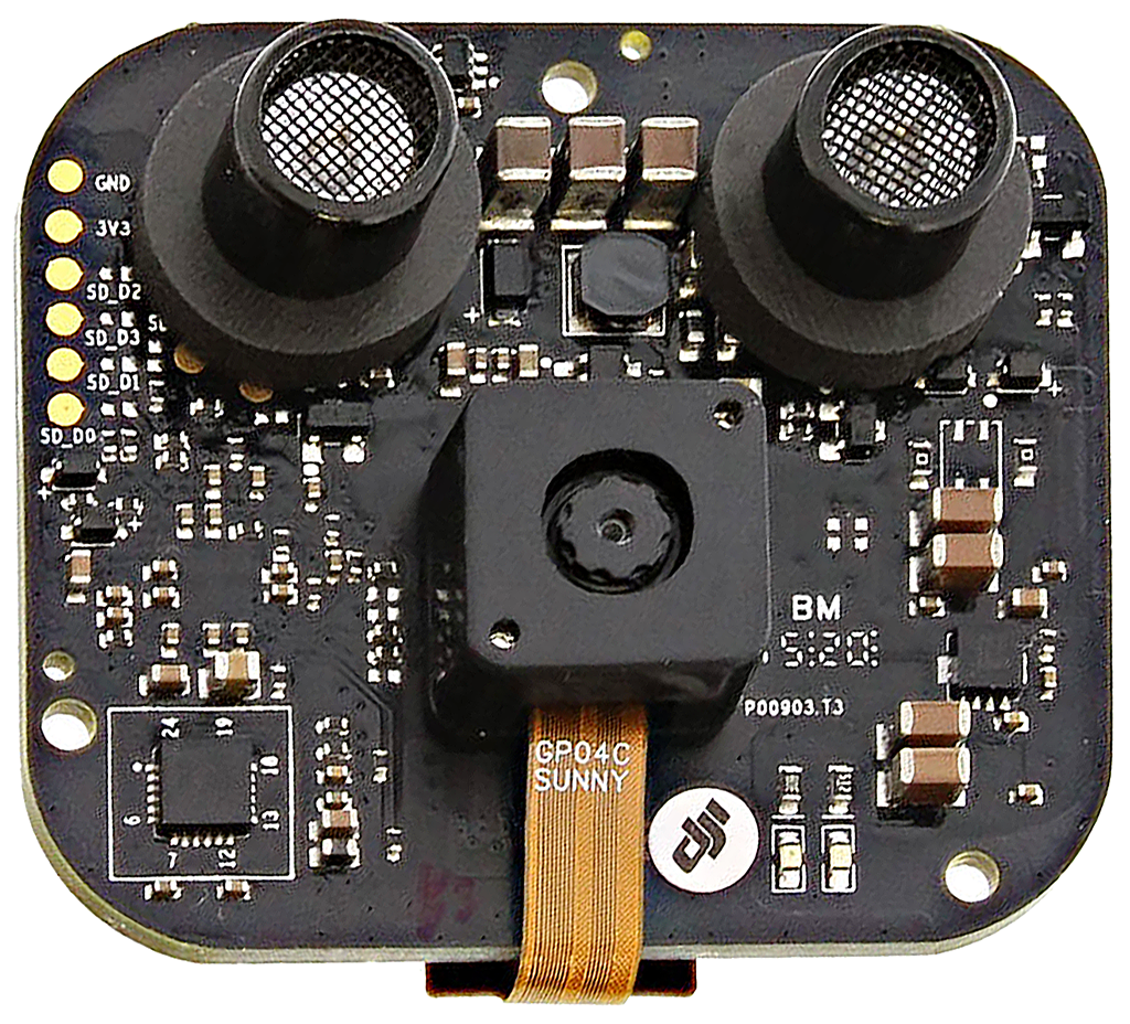
Top of a T3 board:
Bottom of the T3 board:

Top of another T3 board:

Bottom of the T3 board:

Top of a T3 green coated board:
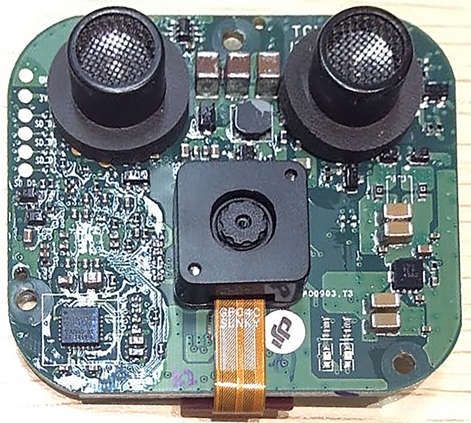
Bottom of the T3 green coated board:

flowchart LR
    Ribbon-ESC((Ribbon<br/>to ESC<br/>Center))
    Ribbon-ESC-- UART<br/>DUML ----VPS-MCU
    subgraph VPS Module
    VPS-MCU[STM32F407<br/>VPS MCU]
    TOF-Driver[M058ZDN uC<br/>ToF driver<br/>ARM Cortex-M0]
    TOF-Driver-Xlat(quartz<br/>oscillator)
    TOF-Comparator[Comparator]
    VPS-Accel-Gyro[MPU-6050<br/>accelerometer<br/>gyroscope]
    VPS-Camera[camera<br/>sensor]
    TOF-Spk((SPK))
    TOF-Mic((MIC))
    TOF-Out-Switch(Output<br/>switches)
    TOF-Inp-Amp[Input<br/>amps]
    TOF-Out-Switch---TOF-Spk
    TOF-Comparator---TOF-Inp-Amp
    TOF-Comparator---TOF-Out-Switch
    TOF-Inp-Amp---TOF-Mic
    TOF-Driver---TOF-Comparator
    TOF-Driver---TOF-Out-Switch
    TOF-Driver-Xlat---TOF-Driver
    TOF-Driver-Xlat---VPS-MCU
    VPS-MCU---TOF-Driver
    VPS-MCU---VPS-Accel-Gyro
    VPS-MCU------VPS-Camera
    end
No schematics available.