WM320 Gimbal driver roll
Function
Variants
Parts
Programming
External interfaces
Service interfaces
Board view
Schematics
The Gimbal Driver Roll board contains ICs to drive the Roll Motor.
Boards for P3X start from V3, as older versions were for P2V. Each roll board variant has a corresponding pitch board variant.
| Marking | Overview |
|---|---|
| Driver Roll V2 | Phantom 2 Vision+ |
| Driver Roll V3 | Phantom 3 Pro/Adv early |
| P00953.04 | Phantom 3 Pro/Adv update 1 |
| P00953.05 | Phantom 3 Pro/Adv update 2 |
| Marking | Amt. | Pkg. | Function | Specification |
|---|---|---|---|---|
| HV232Q 4CM ACVS G4 | 1 | 3.3V CAN transceiver | datasheet | |
| RC43 | 1 | |||
| MPFA 3606 967 M | 1 | |||
| T120 MeMo | 1 | Quartz oscillator, 12 MHz | ||
| ADEF 044/ ADEE 817 | 3 | MP1907GQ QFN10; 100V, 2.5A, High Frequency Half-bridge Gate Driver | description | |
| 7804 GV5K18 | 3 | AON7804 30V Dual N-Channel MOSFET; motor control transistors | datasheet | |
| DSPIC33 EP32 MC504 15095 | 1 | digital signal controller; 70 MIPS core with integrated DSP and enhanced on-chip peripherals; 44/VTLA package; motor control MCU | description | |
| pot-3 | 1 | RDC506002A potentiometer; resistance 6 - 10 kOhm; used for sensing arm position | description datasheet |
| Marking | Amt. | Pkg. | Function | Specification |
|---|---|---|---|---|
| HV232Q 57D ABD5 G4 | 1 | 3.3V CAN transceiver | datasheet | |
| DRV8313 571C AQKP | 1 | 2.5A Three Phase Brushless DC Motor Driver (PWM Ctrl) | description | |
| T120 | 1 | Quartz oscillator, 12 MHz | ||
| pot-3 | 1 | RDC506002A potentiometer; resistance 6 - 10 kOhm; used for sensing arm position | description datasheet |
| Chips | Firmware | Description |
|---|---|---|
| DSPIC33 | gimbal arm Firmware | Gimbal roll control; reads roll arm position potentiometer and supplies control signal to the motor driver circuit. Pre-programmed and not included in firmware updates. |
There are two connectors on the board:
| Marking | Overview |
|---|---|
| 14-pin FFC con. | Flex flat cable connector |
| 10-pin FFC con. | Flex flat cable connector; supplies 12V power and CAN bus connection |
The following service pads exist on this board:
| Marking | Overview |
|---|---|
| PGND | |
| A | |
| B | |
| C | |
| 12V | |
| 5V | |
| 3V3 | |
| CAN_H | |
| CAN_L | |
| PGEC | |
| PGED | |
| CLT | |
| HSA1 | |
| HSA2 | |
| HSA3 | |
| GND |
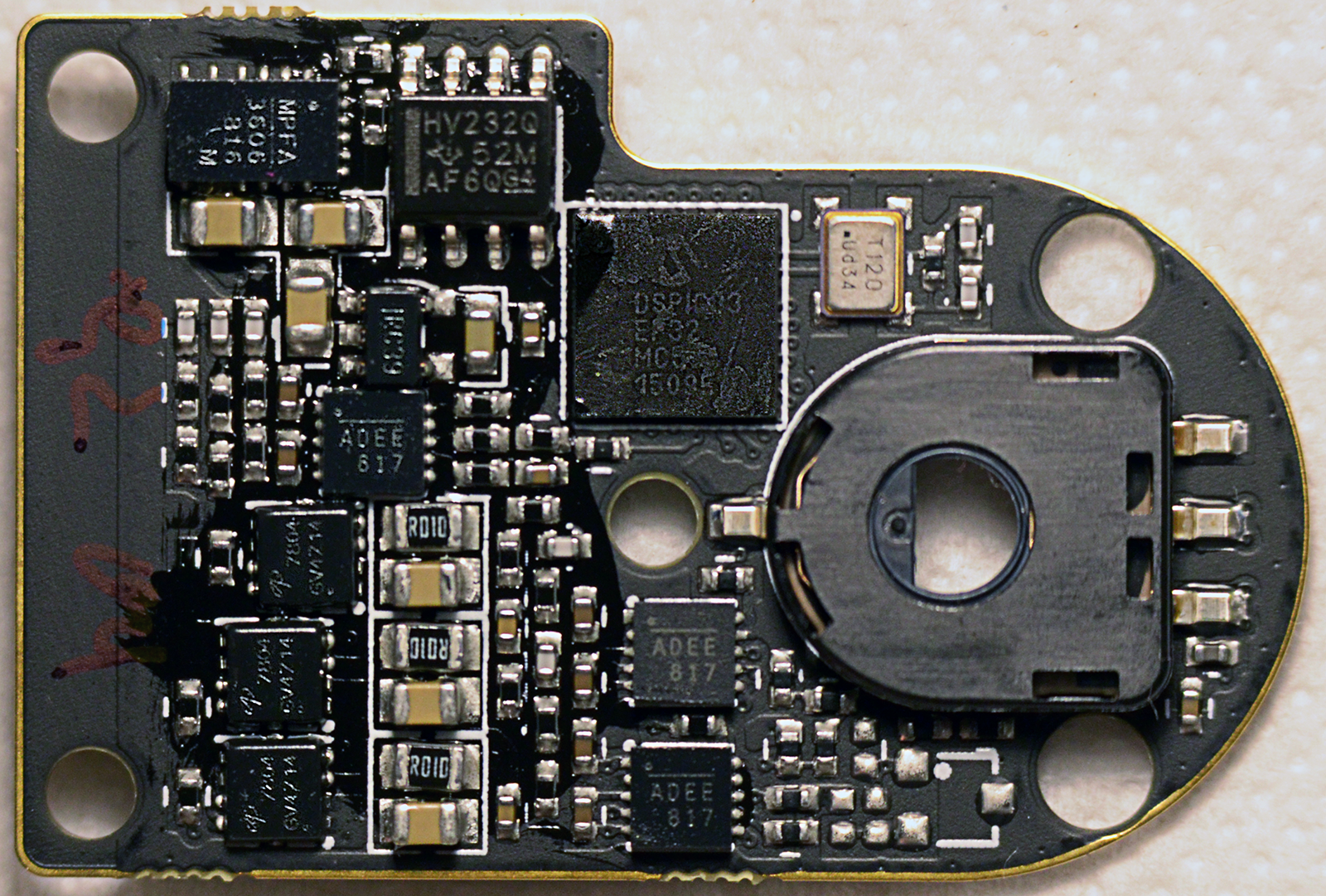
Top of a Driver Roll V3 board:

Bottom of the Driver Roll V3 board:

Top of a second Driver Roll V3 board:

Bottom of the Driver Roll V3 board:

Top of a third Driver Roll V3 board:

Bottom of the third Driver Roll V3 board:
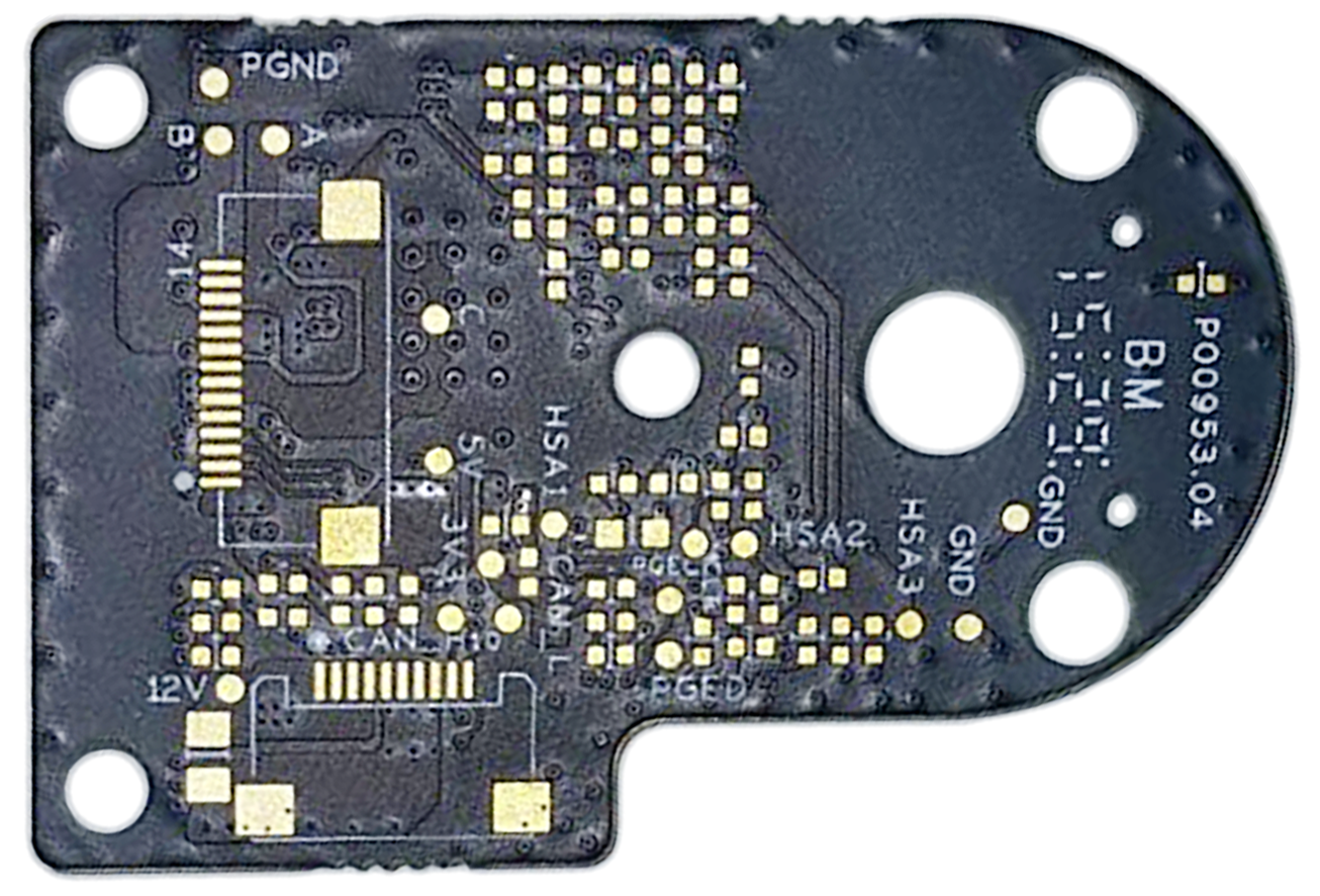
Top of a P00953.04 board:
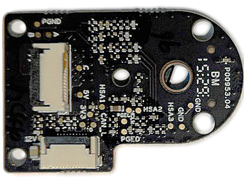
Bottom of the P00953.04 board:

Top of a second P00953.04 board:
Bottom of the P00953.04 board:
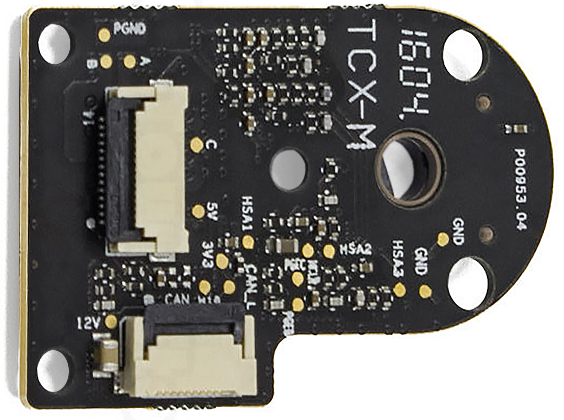
View on the P00953.04 clean PCB (without components):

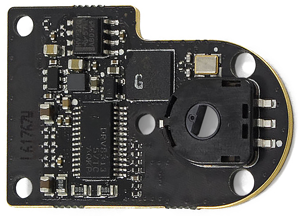
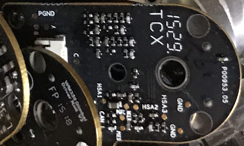
Top of the P00953.05 board:
flowchart LR
    Gimbal-FFC-cable((FFC))-- CAN<br/>bus ---GDR-CAN-tx/rx[CAN<br/>tx/rx]
    subgraph Gimbal driver roll
    GDR-CAN-tx/rx[CAN<br/>tx/rx]---GDR-uC[uC<br/>DSPIC33]
    GDR-Xlat(quartz<br/>oscillator)---GDR-uC
    subgraph BLDC IC / MOSFETs
    GDR-motor-mosfet-pair-a(2x<br/>n-MOS)
    GDR-motor-mosfet-pair-b(2x<br/>n-MOS)
    GDR-motor-mosfet-pair-c(2x<br/>n-MOS)
    GDR-half-bridge-driver-a[half-bridge<br/>driver]
    GDR-half-bridge-driver-b[half-bridge<br/>driver]
    GDR-half-bridge-driver-c[half-bridge<br/>driver]
    GDR-half-bridge-driver-a---GDR-motor-mosfet-pair-a
    GDR-half-bridge-driver-b---GDR-motor-mosfet-pair-b
    GDR-half-bridge-driver-c---GDR-motor-mosfet-pair-c
    end
    GDR-uC---GDR-half-bridge-driver-a
    GDR-uC---GDR-half-bridge-driver-b
    GDR-uC---GDR-half-bridge-driver-c
    GDR-uC---GDR-potentiometer
    GDR-potentiometer(potentiometer)
    end
    GDR-brushless-motor((roll<br/>brushless<br/>motor))
    GDR-potentiometer-. shaft<br/>position .-GDR-brushless-motor
    GDR-motor-mosfet-pair-a---GDR-brushless-motor
    GDR-motor-mosfet-pair-b---GDR-brushless-motor
    GDR-motor-mosfet-pair-c---GDR-brushless-motor
The driver receives commands in form of CAN packets, and sends back momentary position and status. The packets are composed by the small micro-controller, which drives gates on pairs of MOS transistors providing proper phases for the motor. The MOS transistors can be either discrete parts with separate half-bridge drivers, or closed within one dedicated chip - depending on version of the board. The micro-controller also receives feedback by reading a potentiometer which is attached to shaft of the motor.
The following schematics were made by enthusiasts: