-
Notifications
You must be signed in to change notification settings - Fork 401
WM220 GPS Module board
Function
Variants
Parts
Programming
External interfaces
Service interfaces
Board view
Schematics
The GPS module receives messages from GNSS satellites and provides the Flight Controller with current global coordinates.
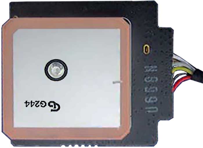
The GPS Patch Antenna usually has factory cut-ins to improve impedance match. One corner of the antenna is also cut, to widen bandwidth. The antenna is excited through a coaxial line, from other side of the board.
There are multiple versions of the board:
| Marking | Overview |
|---|---|
| P01559.08 |
| Marking | Amt. | Pkg. | Function | Specification |
|---|---|---|---|---|
| INPAQ G244 | 1 | Ceramic patch antenna for GNSS band |
The u-blox modules are programmable, but there is no capability of updating GPS firmware via WM220 firmware package.
| Chips | Firmware | Description |
|---|---|---|
| todo | n/a |
Connector on the board is:
| Marking | Overview |
|---|---|
| Tied 6 Wires | Supplies power and allows I/O with the board |
Here is the connector pinout:
| Pin | Label | Function |
|---|---|---|
| 1 | SDA | I2C data line |
| 2 | SCL | I2C clock line |
| 3 | TX | UART Transmit |
| 4 | RX | UART Receive |
| 5 | GND | Ground |
| 6 | +5V | Power to GPS board |
The following service pads exist on this board:
| Marking | Overview |
|---|---|
| TODO |
Top of a P01559.08 board, antenna visible:
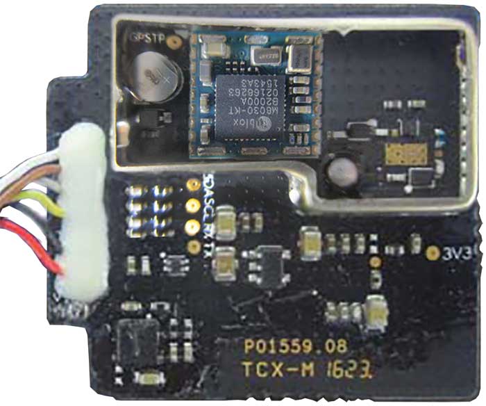
Bottom of the P01559.08 board, SMD components visible:
No schematics available.
This page is created by drone enthusiasts for drone enthusiasts.
If you see a mistake, or you know more about specific subject, or you see an area for improvement for the wiki - create an issue in this project and attach your patch (or describe the change you propose).

