P3X ESC center board
Function
Variants
Parts
Programming
External interfaces
Service interfaces
Board view
Schematics
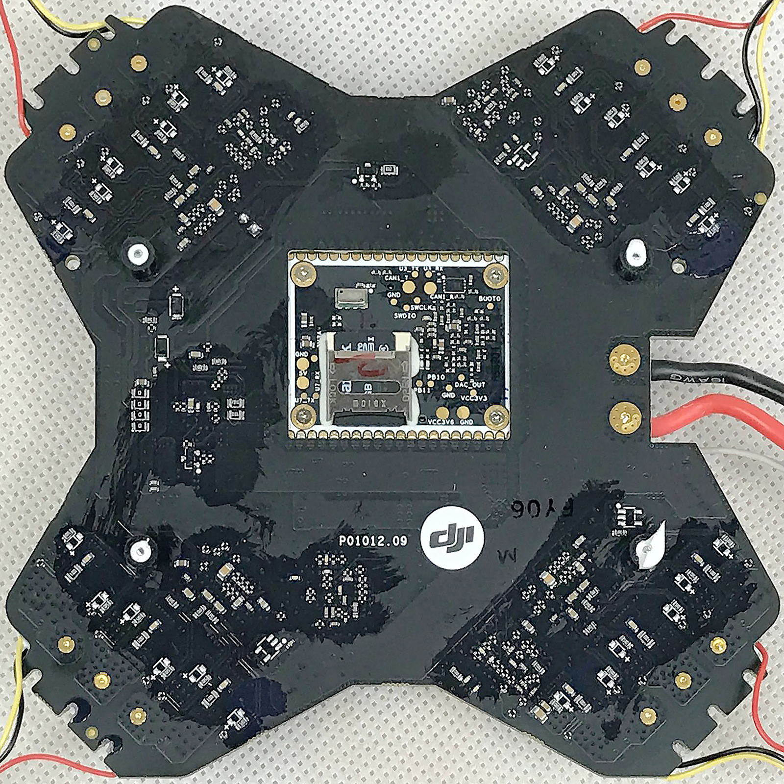
The ESC & Center board contains all four Electronic Speed Control circuits of the quadcopter. Flight controller (also called Main Controller) is placed on a separate board, soldered at the top of the ESC & Center board. This board also contains a few voltage regulators, and acts as a relay for connectors which link all other modules to the Flight Controller and provide them with power.
There are multiple versions of the board, divided into two major lines.
| Marking | Overview |
|---|---|
| WM320_ESC_CENT_v4 | Part P3-33, release version for original 2312 motors |
| P01012.07 | |
| P01012.09 | Part P3-96, modified version for updated 2312A motors |
| Marking | Amt. | Pkg. | Function | Specification |
|---|---|---|---|---|
| WE 7443551920 D5604 | 1 | WE-HCI SMD Flat Wire High Current Inductor | datasheet | |
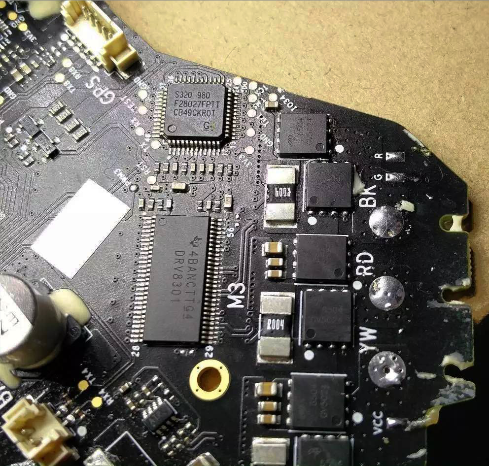
| 54AXVTT G4 DRV8301 | 4 | 3-Phase Brushless Motor Pre-Driver with Dual Current Sense Amps and Buck Converter | description | |
| AON 6504 GA5P1P | 6x4 | 30V 85A N-Channel AlphaMOS | datasheet | |
| Dji IESC2000 CB58APCVT 980 | 4 | Electronic Speed Control MCU; rebranded S320 980 F28027FPTT CB49CKR0T; TMS320F28027F Piccolo Microcontroller with InstaSPIN-FOC | description | |
| 585379 357 XY 434 | 1 | 8-legged chip; two transistors for LM25116? | ||
| S2AJ3 LM25116 32 / 56A3F7U LM25116 MH | 1 | LM25116 6-42V Wide Vin, Current Mode Synchronous Buck Controller; used to prepare 12V line | description | |
| CAP PY 220 V TZ | 3 | electrolytic capacitor | ||
| W1A 53 | 4 | PMST3904 NPN switching transistor; used for LED driving | description | |
| 312FV | 4 | 8-legged chip | ||
| 54531 TI 56A | 2 | TPS54531 3.5V to 28V Input, 5A, 570kHz Step-Down Converter with Eco-mode; used to prepare 5V and 3V8 lines | description | |
| 6524 GV5024 | 24 | ESC High Power MOSFET | ||
| ATP | 4 | PDSO-G8 | OPA2374 Dual rail-to-rail I/O CMOS operational amplifier | description |
| 3-pin USB con. | 1 | MB03B-GHS-TBT; JST GH series top entry connector, pitch 1.25mm, 3-pin | description | |
| 8-pin Gimbal con. | 1 | MB08B-GHS-TBT; JST GH series top entry connector, pitch 1.25mm, 8-pin | description | |
| 5-pin Compass con. | 1 | MB05B-GHS-TBT; JST GH series top entry connector, pitch 1.25mm, 5-pin | description | |
| 10-pin OFDM con. | 1 | MB10B-GHS-TBT; JST GH series top entry connector, pitch 1.25mm, 10-pin | description | |
| 5-pin GPS con. | 1 |
| Marking | Amt. | Pkg. | Function | Specification |
|---|---|---|---|---|
| 7804 GV5V1E | 1 | 8-legged chip; two transistors for LM25116? |
| Chips | Firmware | Description |
|---|---|---|
| IESC2000 (TMS320F28027F) | m1200-m1203 | Electronic speed control programming. |
Connectors on the board are:
| Marking | Overview |
|---|---|
| M1 YW/RD/BK | Motor 1 soldering pads |
| M2 BK/RD/YW | Motor 2 soldering pads |
| M3 YW/RD/BK | Motor 3 soldering pads |
| M4 BK/RD/YW | Motor 4 soldering pads |
| M1 VCC/G/R | LED Light 1 power |
| M2 VCC/G/R | LED Light 2 power |
| M3 VCC/G/R | LED Light 3 power |
| M4 VCC/G/R | LED Light 4 power |
| VCC/GND/BAT | Battery soldering pads and 2-pin connector |
| 3-pin USB con. | micro-USB socket ribbon cable connector; provides USB-to-TTL converter connected to Flight Controller, were DUML communication to external PC takes place; comm parameters are 9600 8N1 |
| 8-pin Gimbal con. | Gimbal top board ribbon cable connector |
| 5-pin Compass con. | Compass ribbon cable connector; only 4 pins used |
| 10-pin OFDM con. | OFDM Module ribbon cable connector; also provides VPS connection |
| 3-pin API con. | API expansion interface; connector not soldered; purpose not fully known |
| 21+20 pin edge pads | FC daughterboard solder pads; the pads are soldered directly to the Flight Controller aka MC |
Here is the connector pinout:
| Pin | Label | Function |
|---|---|---|
| 1-4 | GND | Ground for the Gimbal power; see service pad FRONT GND |
| 5-8 | 12V | Power supply to Gimbal; see service pad FRONT 12V |
Here is the connector pinout:
| Pin | Label | Function |
|---|---|---|
| 1 | SCL3 | |
| 2 | GND | |
| 3 | HDRDY | |
| 4 | 3V6 | |
| 5 | SDA3 |
Here is the connector pinout:
| Pin | Label | Function |
|---|---|---|
| 1,2 | GND | |
| 3,4 | 5V | |
| 5 | TX1 | |
| 6 | RX1 | |
| 7 | GND | |
| 8 | TX6 | |
| 9 | RX6 | |
| 10 | 5V |
Here is the 20-pin side pinout:
| Pin | Label | Function |
|---|---|---|
| 1 | PWM2 | Motor 2 Pulse Width Modulation throttle line; see service pad Mx PWMx |
| 2 | GND | |
| 3 | USB DP | |
| 4 | USB DM | |
| 5 | M12_R | Motor 1&2 Red LED enable signal |
| 6 | GND | |
| 7 | U3_RX | |
| 8 | U3_TX | |
| 9 | GND | |
| 10 | PWM1 | Motor 1 Pulse Width Modulation throttle line; see service pad Mx PWMx |
| 11 | GND | |
| 12 | SCL3 | |
| 13 | SDA3 | |
| 14 | HDRDY | |
| 15 | GND | |
| 16 | TX6 | |
| 17 | RX6 | |
| 18 | GND | |
| 19 | TX1 | |
| 20 | RX1 |
And the 21-pin side pinout:
| Pin | Label | Function |
|---|---|---|
| 1 | M12_G | Motor 1&2 Green LED enable signal |
| 2 | U7_TX | |
| 3 | U7_RX | |
| 4 | GND | |
| 5 | PWM4 | Motor 4 Pulse Width Modulation throttle line; see service pad Mx PWMx |
| 6 | GND | |
| 7 | U8_RX | |
| 8 | U8_TX | |
| 9 | INT | |
| 10 | 3V6 | |
| 11 | GND | |
| 12 | BATT | |
| 13 | GND | |
| 14 | 5V | |
| 15 | M34_G | Motor 3&4 Green LED enable signal |
| 16 | M34_R | Motor 3&4 Red LED enable signal |
| 17 | PWM3 | Motor 3 Pulse Width Modulation throttle line; see service pad Mx PWMx |
| 18 | GND | |
| 19 | U4_TX | |
| 20 | U4_RX | |
| 21 | GND |
The following service pads exist on this board:
| Marking | Overview |
|---|---|
| Mx TDO | ESCx(1-4) diagnostic; unknown |
| Mx TCK | ESCx(1-4) diagnostic; unknown |
| Mx TMS | ESCx(1-4) diagnostic; unknown |
| Mx TDI | ESCx(1-4) diagnostic; unknown |
| Mx 3V3 | ESCx(1-4) diagnostic; 3.3V chip power for ESC MCU |
| Mx GND | ESCx(1-4) diagnostic; ground |
| Mx I034 | ESCx(1-4) diagnostic; unknown |
| Mx PWMx | ESCx(1-4) diagnostic; PWMx(1-4) control signal |
| Mx RST | ESCx(1-4) diagnostic; unknown |
| Mx TEST | ESCx(1-4) diagnostic; unknown |
| Mx GND | ESCx(1-4) diagnostic; ground |
| Mx RX | ESCx(1-4) diagnostic; Flight controller to ESCx UART RX |
| Mx TX | ESCx(1-4) diagnostic; Flight controller to ESCx UART TX |
| USB DP | USB diagnostic; DP cable |
| USB DM | USB diagnostic; DM cable |
| GIM RX3 | Gimbal diagnostic; Flight controller to Gimbal UART RX |
| GIM TX3 | Gimbal diagnostic; Flight controller to Gimbal UART TX |
| FRONT GND | General diagnostic; power line ground |
| FRONT 12V | General diagnostic; power line 12V for gimbal connector |
| BAT RX4 | Battery diagnostic; Flight controller to Battery UART RX |
| BAT TX4 | Battery diagnostic; Flight controller to Battery UART TX |
| GPS RX8 | GPS diagnostic; Flight controller to GPS UART RX |
| GPS TX8 | GPS diagnostic; Flight controller to GPS UART TX |
| VIEW RX7 | General diagnostic; Flight controller unknown UART RX |
| VIEW TX7 | General diagnostic; Flight controller unknown UART TX |
| VIEW 5V | General diagnostic; 5V power |
| VIEW GND | General diagnostic; ground |
| VIEW 3V6 | General diagnostic; 3.6V chip power |
| OFDM RX1 | OFDM diagnostic; Flight controller to OFDM UART RX |
| OFDM TX1 | OFDM diagnostic; Flight controller to OFDM UART TX |
| OFDM SDA3 | OFDM diagnostic; unknown |
| OFDM SCLa | OFDM diagnostic; unknown |
| CMPAS RX6 | Compass diagnostic; Flight controller to Compass UART RX |
| CMPAS TX6 | Compass diagnostic; Flight controller to Compass UART TX |
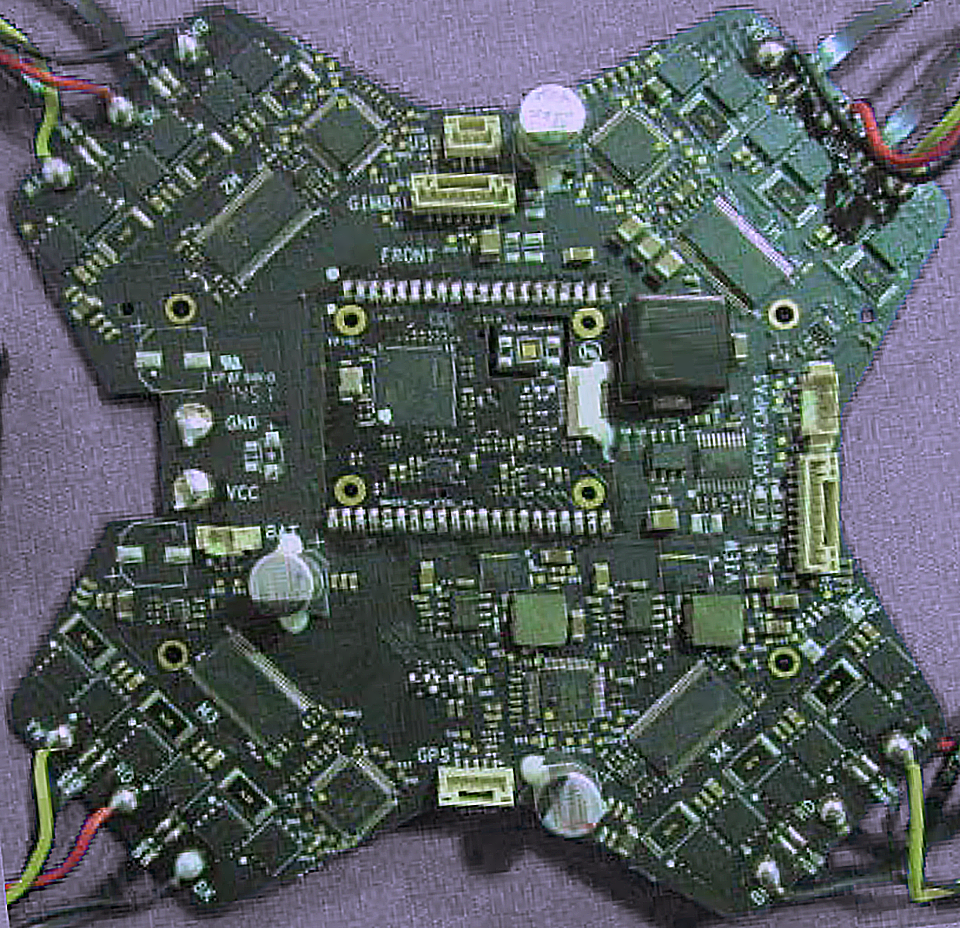
Top of the WM320_ESC_CENT_v4 board:
Bottom of the WM320_ESC_CENT_v4 board:

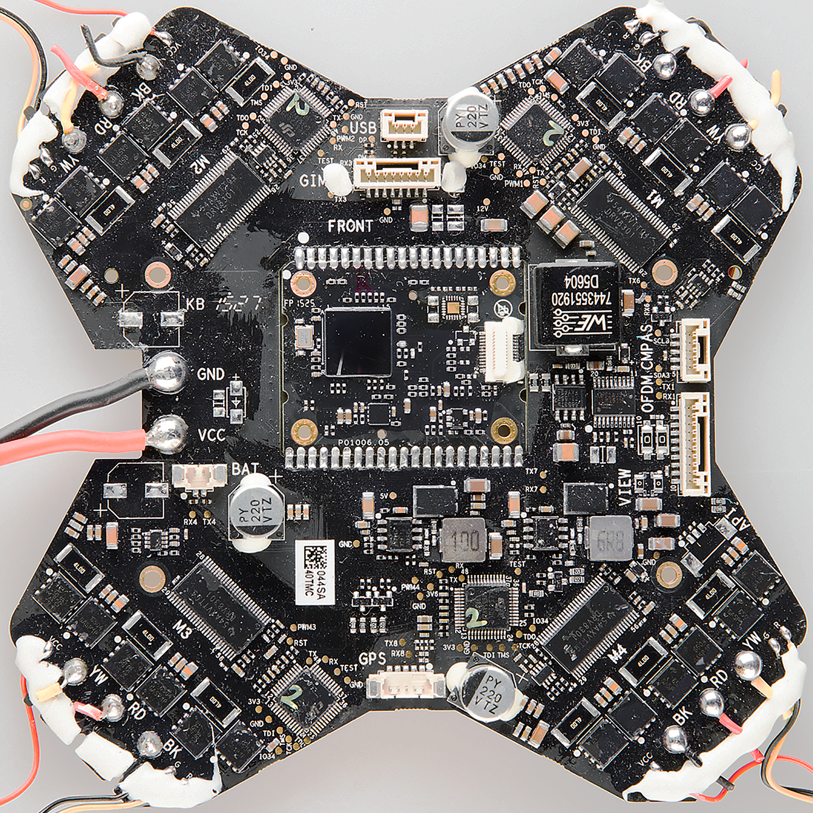
Top of the P01012.07 board:
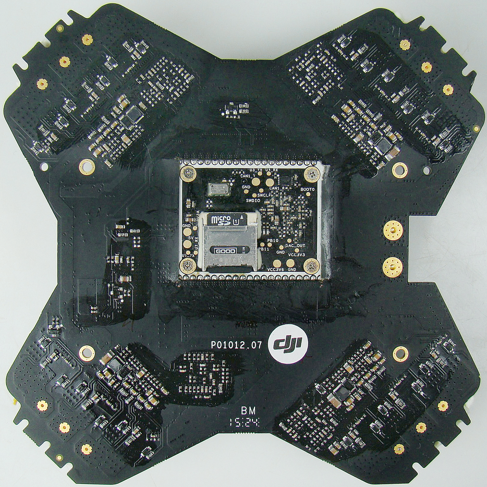
Bottom of the P01012.07 board:
Top of the P01012.07 board, side views:


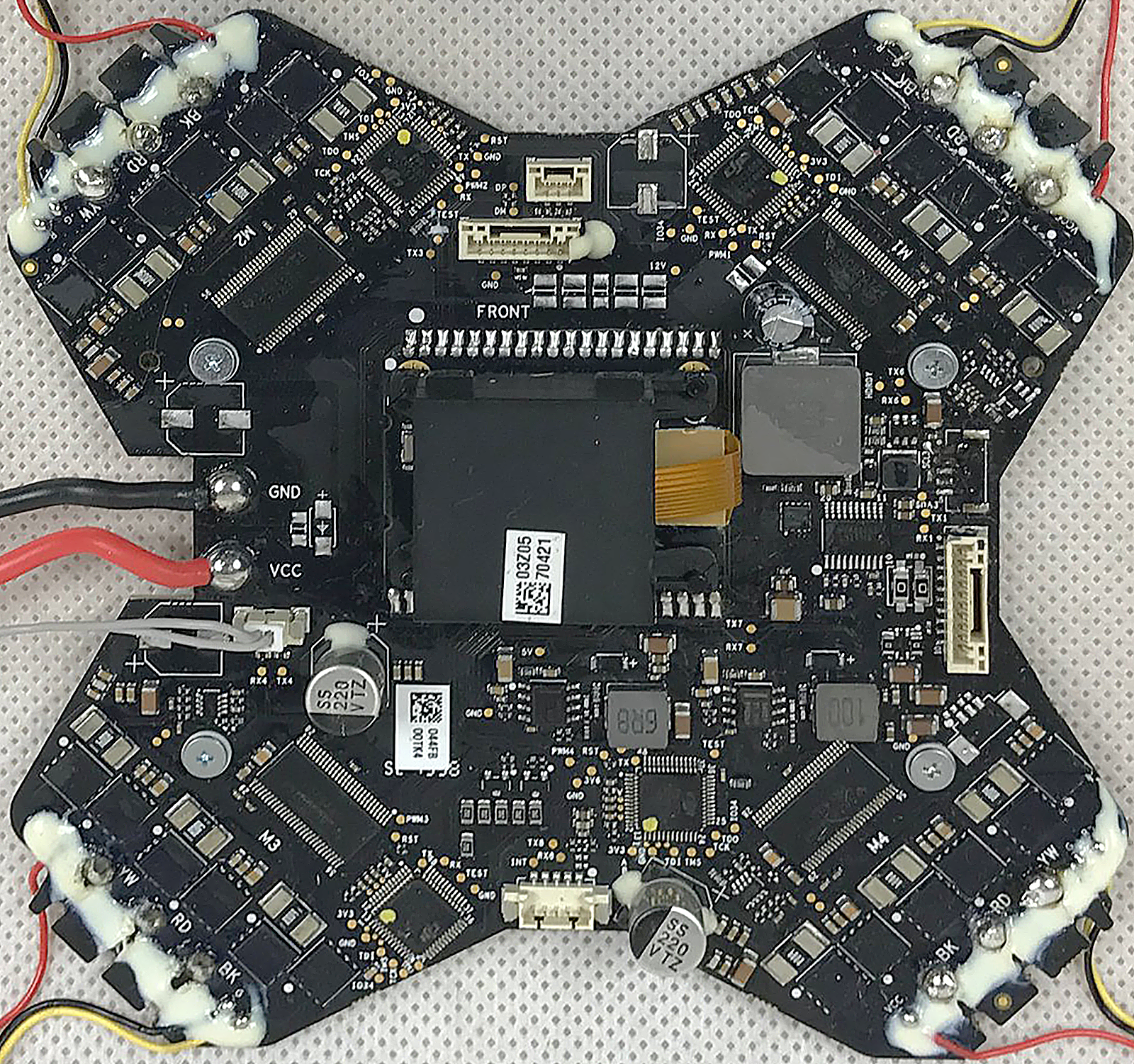
Top of a P01012.09 board:
Bottom of the P01012.09 board:
Top of a 2nd P01012.09 board (crashed - with missing connector and capacitor):

Bottom of the 2nd P01012.09 board:

Top of an unknown board, but with real IESC2000 chip marking:
flowchart LR
    Ribbon-OFDM((ribbon<br/>to OFDM<br/>and VPS))
    FC-USB-Socket((USB<br/>socket<br/>to FC))
    Ribbon-GPS((ribbon<br/>to GPS))
    Ribbon-API((ribbon<br/>to API))
    Ribbon-Compass((ribbon<br/>to<br/>compass))
    Ribbon-OFDM-- UART<br/>DUML ---FC
    Ribbon-GPS---FC
    Ribbon-API---FC
    Ribbon-Compass---FC
    FC-USB-Socket-- USB-to-TTL<br/>DUML ---FC
    subgraph ESC Center board
    subgraph FC Daughterboard
    FC[STM32F<br/>flight<br/>controller]
    end
    FC-- UART<br/>+PWM ---ESC-uC0
    FC-- LED<br/>control<br/>GPIO ---ESC-LED-BJT-pair-0
    ESC-LED-BJT-pair-0(LED control<br/>2x NPN BJT)
    subgraph ESC0
    ESC-uC0[TMS320F<br/>Piccolo 32-Bit uC<br/>motor control]
    ESC-Driver0[DRV8301<br/>3-Ph Motor Drv<br/>PWM Ctrl w/ SPI]
    ESC-MOSFET-pair-YW0[2x 85A<br/>n-MOS]
    ESC-MOSFET-pair-RD0[2x 85A<br/>n-MOS]
    ESC-MOSFET-pair-BK0[2x 85A<br/>n-MOS]
    ESC-uC0---ESC-Driver0
    ESC-Driver0---ESC-MOSFET-pair-YW0
    ESC-Driver0---ESC-MOSFET-pair-RD0
    ESC-Driver0---ESC-MOSFET-pair-BK0
    end
    end
    subgraph Aircraft arm 1
    Quad-LED1(bi-color<br>LED)
    Quad-Motor1((Motor<br/>M1))
    end
    ESC-MOSFET-pair-YW0---Quad-Motor1
    ESC-MOSFET-pair-RD0---Quad-Motor1
    ESC-MOSFET-pair-BK0---Quad-Motor1
    ESC-LED-BJT-pair-0---Quad-LED1
The diagram only contains one Electronic Speed Control circuit and one motor, to avoid duplication. Same goes for the bi-color LED. The ribbon to Gimbal is also skipped, as it contains no control signals, and the diagram does not include power delivery.
The Flight Controller contains a list of internal parameters which are used within the flight control algorithms and other routines. These values can be changed by DUML packets, there are also packets to change current state of flight and control the flight.
ESC circuits are initialized and configured via shared UART, but momentary throttle value is provided to each ESC by separate PWM lines. If any of the ESC micro-controllers does not pass handshake to the FC within a second after power-on, it will start to beep through the motors.
The following schematics were made by enthusiasts: