-
Notifications
You must be signed in to change notification settings - Fork 402
WM232 Main Core Processor board
Function
Variants
Parts
Programming
External interfaces
Service interfaces
Board view
Schematics
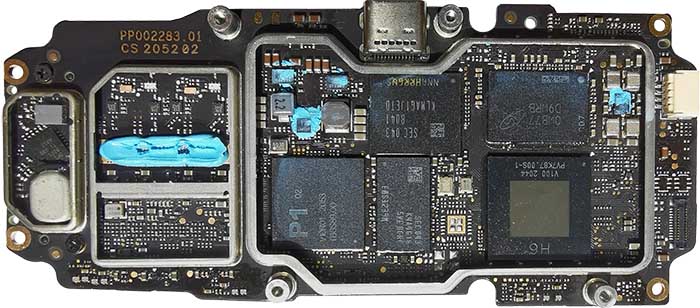
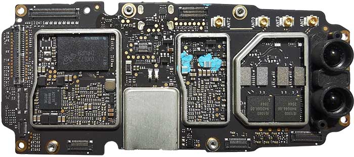
The board stores most of computational power of the drone. It contains video encoder for both FPV and SD-card, but also video recognition for positioning (VPS) and gesture control. It also contains transceiver and high-frequency components.
Several versions of the module are known.
| Marking | Overview |
|---|---|
| PP002283.01 |
| Marking | Amt. | Pkg. | Function | Specification |
|---|---|---|---|---|
| P1 02 V10R01 2053 IBGS89.00 | 1 | "Sparrow", Cortex-M, SDR | ||
| H6 V100 2044 PV7K87.00S-1 | 1 | FBGA | Custom ASIC based on Imagination Technologies IP, Cortex-A7 CPU, PowerVR e5500 encoder, TrustZone | |
| SEC 043 B041 KLMAG1JETD NNAHRRGVS | 1 | 153FBGA 11.5x13 | Samsung KLMAG1JETD-B041 eMMC 128Gbit, eMMC5.1 JEDEC Standard support | description datasheet |
| OPT 3101 TI 086 A212 | 1 | QFN | Texas Instruments OPT3101 ToF-based long-range proximity and distance sensor analog front end | description |
| 213 GAZ | 2 | |||
| 513 GAK | 2 | Not sure if separate chips, or just barely readable 213 GAZ | ||
| 566235 ?081 ? 20 | 2 | barely readable | ||
| BN52.0 D045 | 1 | Quartz Oscillator | ||
| R0.03 D041 | 1 | Quartz Oscillator | ||
| XP38K D041 | 1 | Quartz Oscillator; barely readable | ||
| W1A 06 | 1 | 3-pin SOT-23 | PMBT3904 NPN switching transistor | description |
| 1A w0d | 2 | 6-pin DFN-33 | ||
| 4200 | 1 | 6-pin SOT | ||
| R100 | 1 | SMD Resistor | ||
| IE1000 N40G66.00 2044 | 2 | 5.8GHz RF Amp (both PA and LNA) | ||
| Micron 0XB77 D9WRB IRTI | 2 | Micron MT53E256M32D2DS-053 WT:B 8Gb LPDDR4-3733 | description | |
| ACTIVE 8846QM J02CHL | 1 | Active-Semi Advanced PMIC for Multi-Core Application Processors | description |
| Chips | Firmware | Description |
|---|---|---|
| H6 E1E | m0801 |
| Marking | Overview |
|---|---|
| TODO |
The following service pads exist on this board:
| Marking | Overview |
|---|---|
| TODO |
Top of a PP002283.01 board:
Bottom of the PP002283.01 board:
flowchart LR
    Connector-BAT((batt<br/>connec<br/>tor))
    subgraph Battery Intelligent board
    direction LR
    BatteryBMS[BQ9003 BMS<br/>Li-Ion pack<br/>manager]
    BattFeedbackR(0.01 Ohm<br/>feedback<br/>resistor)
    EnablePackFET(MOSFET<br/>output<br/>control)
    EnableChargeFET(MOSFET<br/>charge<br/>enable)
    EnableDischargeFET(MOSFET<br/>internal<br/>discharge<br/>enable)
    DischargeR(discharge<br/>resistor)
    BatteryButton(button)
    BatteryLEDs(LED line)
    DischargeR---EnableDischargeFET
    BatteryBMS-- DSG ---EnableDischargeFET
    BatteryBMS-- PCHG ---EnablePackFET
    BatteryBMS-- CHG ---EnableChargeFET
    BatteryButton---BatteryBMS
    BatteryLEDs---BatteryBMS
    end
    subgraph Li-Po cells pack
    direction TB
    BatteryCell1(battery<br/>cell 1)
    BatteryCell2(battery<br/>cell 2)
    BatteryCell3(battery<br/>cell 3)
    BatteryTempSense(NTC<br/>thermistor)
    BatteryCell1===BatteryCell2
    BatteryCell3===BatteryCell2
    end
    BattFeedbackR===BatteryCell1
    BatteryBMS-- VSS ---BatteryCell1
    BatteryBMS---BatteryCell2
    BatteryBMS---BatteryCell3
    Connector-BAT== PACK- ===BattFeedbackR
    BatteryBMS-- SRn ---BattFeedbackR
    BatteryBMS-- TS ---BatteryTempSense
    EnableDischargeFET===BatteryCell3
    EnablePackFET===EnableDischargeFET
    EnableChargeFET===EnableDischargeFET
    Connector-BAT== PACK+ ====EnablePackFET
    Connector-BAT== PACK+ ====EnableChargeFET
    Connector-BAT-- SMBus ----BatteryBMS
Thick lines are the ones transferring high power. Feedback resistor for measuring current is inserted into negative line, while all the MOSFET switches are within positive line. The three Li-Po cells are connected in series, so that the voltage sums up.
The output connector includes SMBus lines from the Battery Management System chip, which allow to exchange packets described in Smart Battery Specification, as well as some DJI-specific extensions.
The charge level, as well as errors and faults detected within the BMS, can be shown on four LEDs. Specifics of how the interface and the buttons work, as well as extensions to the SBS protocol, require implementation within the BMS firmware. Therefore, the firmware is not a stock TI version, but a modification of TIs firmware code by DJI engineers.
No schematics available.
This page is created by drone enthusiasts for drone enthusiasts.
If you see a mistake, or you know more about specific subject, or you see an area for improvement for the wiki - create an issue in this project and attach your patch (or describe the change you propose).

