P3 P4 GPS Module board
Function
Variants
Parts
Programming
External interfaces
Service interfaces
Board view
Schematics
The GPS module receives messages from GNSS satellites and provides the Flight Controller with current global coordinates.
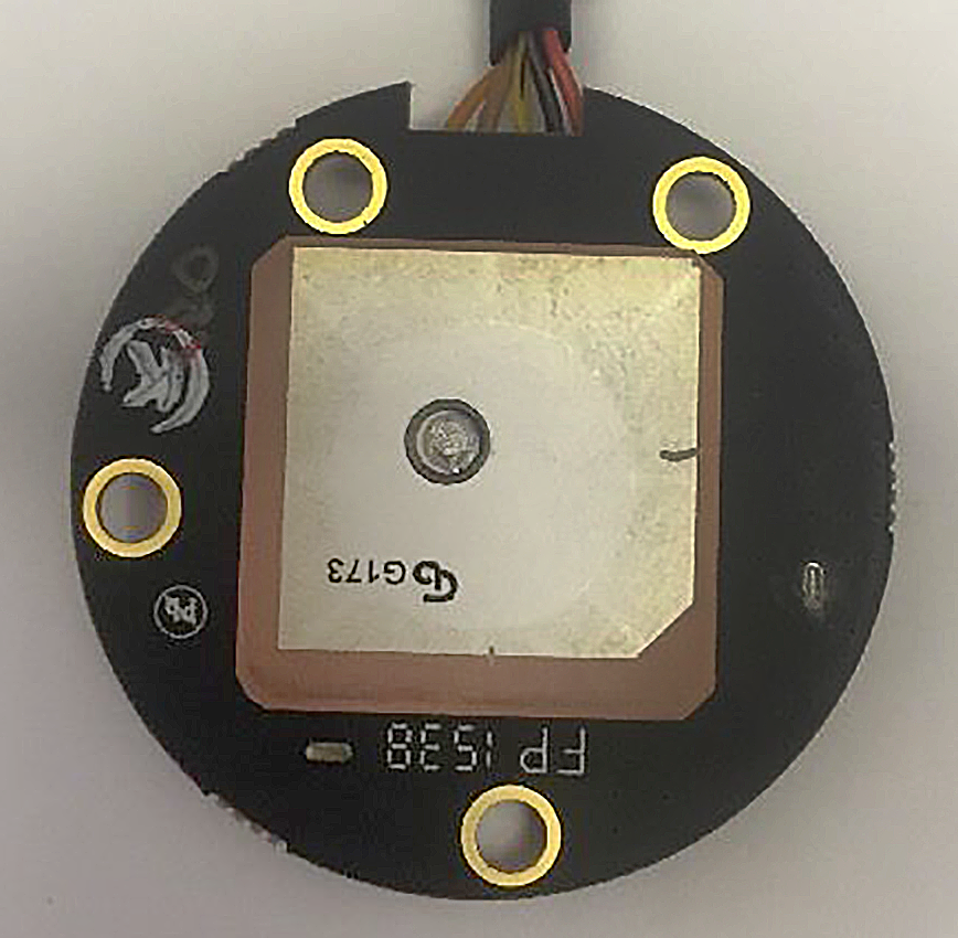
The GPS Patch Antenna usually has factory cut-ins to improve impedance match. One corner of the antenna is also cut, to widen bandwidth. The antenna is excited through a coaxial line, from other side of the board.
There are multiple versions of the board:
| Marking | Overview |
|---|---|
| WM320_GPS_V3_PCB | In the drone submitted for FCC certification. |
| P00857 | Version with u-blox markings on the chip. |
| P01100.06 | Version with Dji markings on the chip. |
| P01100.08 | Minor update. |
| Marking | Amt. | Pkg. | Function | Specification |
|---|---|---|---|---|
| u-blox NEO-6Q-0-0001 | 1 | stand-alone GPS receiver, 50 channels | Datasheet | |
| INPAQ G173 | 1 | Ceramic patch antenna for GNSS band |
| Marking | Amt. | Pkg. | Function | Specification |
|---|---|---|---|---|
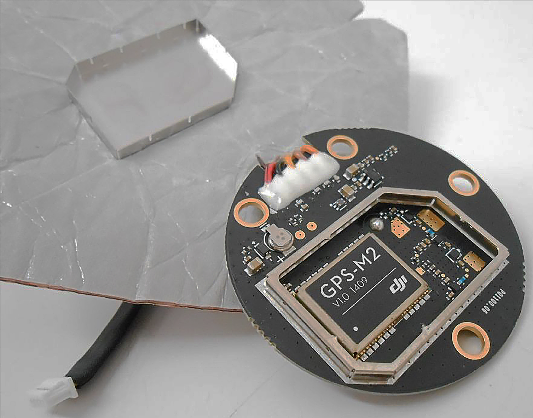
| Dji GPS-M2 v1.0 1409 | 1 | Rebranded u-blox NEO-M8N-0 GNSS receiver, 72 channels, up to 3 GNSS (GPS, Galileo, GLONASS, BeiDou). | Description Datasheet | |
| INPAQ G173 | 1 | Ceramic patch antenna for GNSS band |
The u-blox modules are programmable, but there is no capability of updating GPS firmware via P3X/P3S firmware package.
| Chips | Firmware | Description |
|---|---|---|
| NEO-6Q | n/a | The software computes and sends GPS coordinates according to configuration; the module contains internal ROM, factory programmed. |
| NEO-M8N | u-blox M8 Firmware | The software computes and sends GNSS coordinates according to configuration; module allows programming via serial interface. |
Connector on the board is:
| Marking | Overview |
|---|---|
| 5-wire 1.25mm connector | Used to supply power to the GPS unit and provide communication with the flight controller. UART 3-wire serial interface is used for the communication. |
| Pin | Color | Function |
|---|---|---|
| 0 | red | +3.3V |
| 1 | black | GND |
| 2 | yellow | TX (3.3V) |
| 3 | brown | RX (3.3V) |
| 4 | orange | interrupt (5Hz) |
The following service pads exist on this board:
| Marking | Overview |
|---|---|
| bottom side upper pad | Only exists in some variants of the board. |
| bottom side lower pad A | |
| bottom side lower pad B |
Top of a WM320_GPS_V3_PCB board, antenna visible:

Bottom of the WM320_GPS_V3_PCB board, SMD components visible:

Top of a P00857 board, antenna visible:

Bottom of the P00857 board, SMD components visible:

Top of a P01100.06 board:

Bottom of the P01100.06 board:
Top of a P01100.08 board:
Bottom of the P01100.08 board:

Top of another P01100.08 board, from Phantom 4:

Bottom of the P01100.08 board:

The following schematics were made by enthusiasts: