P3 Battery Intelligent board
Function
Variants
Parts
Programming
External interfaces
Service interfaces
Board view
Schematics
DJI Intelligent Flight Battery for P3 is a 4480mAh, 15.2V LiPo4s HV battery, supporting up to 23 minutes of flight time. The battery also has built-in sensors and bright LEDs that let you know the status and remaining power. It contains automatic discharge feature to avoid swelling (fully charged LiPo cells release hydrogen), and Permanent Failure feature which disables the battery in case of damage or unexpected behavior of cells.
The battery management system chip (TI BQ30Z55) is queried for data by a small micro-controller (TI MSP430) through a Smart Battery System protocol. That micro-controller sends updates to the FC in regard to current battery status.
The SBS protocol defines battery-related commands to be transferred over SMBus, which in turn is deviced from I2C.
There are multiple versions of the board.
| Marking | Overview |
|---|---|
| DJI01-ROF.PCB | |
| DJI0617 Rev 04 (2014-10-23) |
| Marking | Amt. | Pkg. | Function | Specification |
|---|---|---|---|---|
| MSP430 G2755 | 1 | Texas Instruments MSP430 MCU is used to control the battery and external interfaces. | description datasheet | |
| BQ30Z55 | 1 | TSSOP-30 | Integrated 2-Series, 3-Series, and 4-Series Li-Ion or Li-Polymer Cell Battery Pack Manager and Protection; the specific chip was only made available by TI for a few customers, but it is very similar to BQ30Z554. Also, its spec can be found in various places (sluu852a.pdf). | description applc.note |
| CSD17576 TI 551 C2HK E4 | 4 | DNK8 5x6mm | 30V, N channel power MOSFET, 2.9mOhm, 100A; power enable transistors | description |
| 0 2EB1E 1= | 1 | |||
| X16Y 16 | 6 | SOT-3 |
| Chips | Firmware | Description |
|---|---|---|
| unknown | m1100 | First battery model. |
| unknown | m1101 | Updated battery. |
Connectors on the board are:
| Marking | Overview |
|---|---|
| P+/- High Current Soldering Pads | Power output wires of the battery |
| B+/- High Current Soldering Pads | Battery cells connection |
| PAD1/2 Soldering Pads | Temperature sensor connection |
| 7-pin Balancer and UART con. | Contains connections for cells balancing, plus Rx and Tx wires for the serial communication interface connected to Flight Controller via ESC Center Board. |
Here is the connector pinout:
| Pin | Label | Function |
|---|---|---|
| 1 | SCL | incorrectly labelled UART communication RX/TX, 115200 8n1 |
| 2 | SDA | incorrectly labelled UART communication TX/RX |
| 3 | B- | Cells negative terminal |
| 4 | B1 | Cells balancing 1 |
| 5 | B2 | Cells balancing 2 |
| 6 | B3 | Cells balancing 3 |
| 7 | B+ | Cells positive terminal |
Despite some misleading markings on some boards, the communication to FC is through UART, not I2C.
The following service pads exist on this board:
| Marking | Overview |
|---|---|
| SCL | UART line (yes, really) from the 7-pin Balancer and UART con. |
| SDA | UART line (yes, really) from the 7-pin Balancer and UART con. |
| B1+ | Cells balancing line from the 7-pin Balancer and UART con. |
| B4+ | Cells balancing line from the 7-pin Balancer and UART con. |
| BD | |
| SW | |
| GND | Ground reference for the I2C communication |
| SMBD | I2C data line for SMBus communication with BMS chip |
| SMBC | I2C clock line for SMBus communication with BMS chip |
| NTC1 | |
| RES | |
| Pres | |
| VCC | |
| TEST |
Top of a DJI01-ROF board:

Bottom of the DJI01-ROF board:
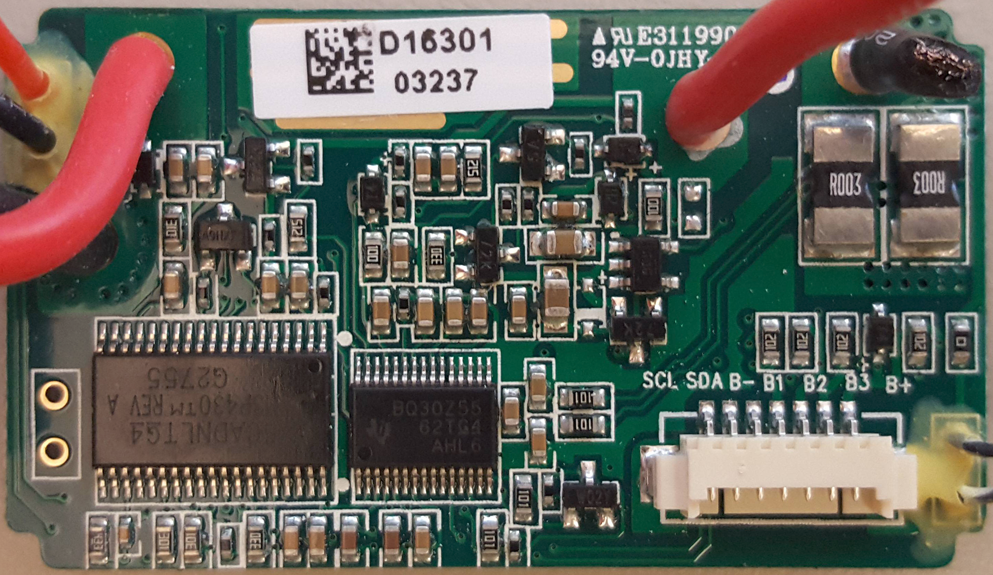
Top of a DJI0617_Rev_04 board:

Bottom of the DJI0617_Rev_04 board:

Top of another DJI0617_Rev_04 board:

Bottom of the DJI0617_Rev_04 board:

flowchart LR
    Connector-BAT((batt<br/>connec<br/>tor))
    subgraph Battery Intelligent board
    direction LR
    BatteryMCU[MSP430 MCU<br/>Battery<br/>interface<br/>control]
    BatteryBMS[BQ30Z55 BMS<br/>Li-Po pack<br/>manager]
    BattFeedbackR(0.015 Ohm<br/>feedback<br/>resistor)
    BatteryButton(button)
    BatteryLEDs(LED line)
    BatteryMCU-- GPIO ---BatteryButton
    BatteryMCU-- GPIO ---BatteryLEDs
    EnablePackFET(MOSFET<br/>output<br/>control)
    EnableChargeFET(MOSFET<br/>charge<br/>enable)
    EnableDischargeFET(MOSFET<br/>internal<br/>discharge<br/>enable)
    DischargeR(discharge<br/>resistor)
    DischargeR---EnableDischargeFET
    BatteryBMS-- DSG ---EnableDischargeFET
    BatteryMCU-- SMBus ---BatteryBMS
    BatteryBMS-- GPOD ---EnablePackFET
    BatteryBMS-- CHG ---EnableChargeFET
    end
    subgraph Li-Po cells pack
    direction TB
    BatteryCell1(battery<br/>cell 1)
    BatteryCell2(battery<br/>cell 2)
    BatteryCell3(battery<br/>cell 3)
    BatteryCell4(battery<br/>cell 4)
    BatteryTempSense(NTC<br/>thermistor)
    BatteryCell1===BatteryCell2
    BatteryCell3===BatteryCell2
    BatteryCell4===BatteryCell3
    end
    BattFeedbackR===BatteryCell1
    BatteryBMS-- VSS ---BatteryCell1
    BatteryBMS---BatteryCell2
    BatteryBMS---BatteryCell3
    BatteryBMS---BatteryCell4
    Connector-BAT== PACK- ===BattFeedbackR
    BatteryBMS-- SRn ---BattFeedbackR
    BatteryBMS-- TS ---BatteryTempSense
    EnableDischargeFET===BatteryCell4
    EnablePackFET===EnableDischargeFET
    EnableChargeFET===EnableDischargeFET
    Connector-BAT== PACK+ ===EnablePackFET
    Connector-BAT== PACK+ ===EnableChargeFET
    Connector-BAT-- UART ---BatteryMCU
Thick lines are the ones transferring high power. Feedback resistor for measuring current is inserted into negative line, while all the MOSFET switches are within positive line. The four Li-Po cells are connected in series, so that the voltage sums up.
The Battery Management System chip is not designed to have any user interface, so that is handled by the additional micro-controller. The MCU communicates with BMS using the protocol described in Smart Battery Specification, over SMBus interface. The charge level, as well as errors retieved from the BMS, can be shown on attached line of four LEDs. The MCU can also read button state, and ask the BMS to start or shutdown the power delivery.
No schematics available.