-
Notifications
You must be signed in to change notification settings - Fork 402
SR6 Main board
Function
Variants
Parts
Programming
External interfaces
Service interfaces
Board view
Schematics
The SR6 radio transmitter contains all vital elements on one board. The board is responsible of reading state of control sticks and switches, doing proper ADC conversion, then transmitting the control signal.
Known variants of the board:
| Marking | Overview |
|---|---|
| 2021-10-16 | The usual SR6 board. |
| Marking | Amt. | Pkg. | Function | Specification |
|---|---|---|---|---|
| CYRF6936 | 1 | Transceiver | ||
| Nuvoton MINI54ZAN | 1 | ARM Cortex™-M0 32-bit microcontroller | datasheet | |
| HYDZ | 1 | Piezoelectronic Buzzer |
| Chips | Firmware | Description |
|---|---|---|
| ? | TODO |
Connectors on the board are:
| Marking | Overview |
|---|---|
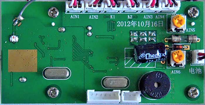
| 3-pin AIN1 | |
| 3-pin AIN2 | |
| 3-pin K1 | |
| 3-pin K2 | |
| 3-pin AIN3 | |
| 3-pin AIN4 | |
| 6-pin MOLEX at bottom | ICE Serial wired debugger connector |
| 3-pin MOLEX at bottom | Auxiliary GPIO connector |
Here is the connector pinout:
| Pin | Label | Function |
|---|---|---|
| 1 | VCC | |
| 2 | ICE_DAT | |
| 3 | ICE_CLK | |
| 4 | !RESET | |
| 5 | GND | |
| 6 | GND |
Here is the connector pinout:
| Pin | Label | Function |
|---|---|---|
| 1 | P2.3 | |
| 2 | GND | |
| 3 | P2.4 |
Some of RC button combinations have special functions.
| Combination | Overview |
|---|---|
| TODO |
The following service pads exist on this board:
| Marking | Overview |
|---|---|
| TODO |
Top of a 2021-10-16 board:
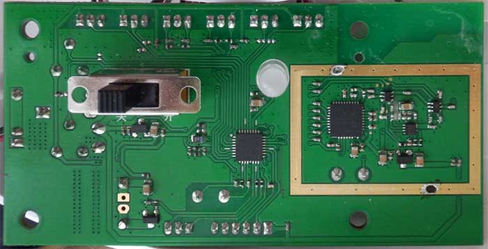
Bottom of the 2021-10-16 board:
No schematics available.
This page is created by drone enthusiasts for drone enthusiasts.
If you see a mistake, or you know more about specific subject, or you see an area for improvement for the wiki - create an issue in this project and attach your patch (or describe the change you propose).

