P3 Flight Controller aka MC
Function
Variants
Parts
Programming
External interfaces
Service interfaces
Board view
Schematics
Flight controller (also called Main Controller) board is soldered at the top of the ESC center board. Its CPU runs Real-Time Operating System which acquires readings from all sensors and sends control signals to motors ESC units. The same controller board can be mounted on P3C, P3X and P3S esc center boards.
There are multiple versions of the board.
| Marking | Overview |
|---|---|
| P01006.05 |
| Marking | Amt. | Pkg. | Function | Specification |
|---|---|---|---|---|
| MP65 F404E1 L1343 | 1 | Inertial measurement unit; MPU-6500 QFN Accelerometer gyroscope sensor | description | |
| STM32F427IIH6 HPAAT VG KOR HP 528 | 1 | ARM Cortex-M4 core with DSP and FPU, 2 Mbytes Flash, 180 MHz CPU, ART Accelerator, Chrom-ART Accelerator, FMC with SDRAM | description | |
| MEAS M3710J 560702 BA03 | 1 | QFN-8 | MS5607-02BA03 barometer/pressure sensor, 10-1.2BAR | datasheet |
| PA 5fA | 1 | 3x3 UDFN/WSON | Mini Linear Regultor; part used is DI AP7361ADJ, but it could also be TI TPS7A16; used to power uC and SD card slot | DI datasheet TI description |
| RC09 | 1 | SOT-5 | Buck Converter | |
| 3E AH C | 1 | 8-pin | Atmel ATSHA204 CryptoAuthentication? | |
| VS6 | 1 | SOT-3 | Unknown; part of IMU circuit |
| Marking | Amt. | Pkg. | Function | Specification |
|---|---|---|---|---|
| MP65 V179C1 L1508 | 1 | Inertial measurement unit; MPU-6500 QFN Accelerometer gyroscope sensor | description | |
| STM32F427IIH6 | 1 | ARM Cortex-M4 core with DSP and FPU, 2 Mbytes Flash, 180 MHz CPU, ART Accelerator, Chrom-ART Accelerator, FMC with SDRAM | description | |
| MEAS M3710J 560702 BA03 | 1 | QFN-8 | TE Connectivity MS5607 Barometer/pressure sensor, 10-1.2BAR | description |
See P3 Flight Controller aka MC repair for repair instructions of this board.
| Chips | Firmware | Description |
|---|---|---|
| STM32F427IIH6 | m0305, m0306 | Flight controller (MC) programming, loader(05) and application(06). |
Connectors on the board are:
| Marking | Overview |
|---|---|
| 21+20 pin edge pads | The pads are soldered directly to the ESC center board, providing power and communication with the rest of the drone. |
| 24-pin FFC con. | Flex flat cable connector for the sensors mounted within the flight controller plastic case. |
| Molex micro-SD card slot | For inserting the SD-card for storing flight logs. This card only stores logs, any videos and photos are kept on another SD-card, within gimbal. Old logs are automatically removed to make place for new ones. The card slot latch is glued with silicon. It is possible to control the card content by DUML commands. |
The following service pads exist on this board:
| Marking | Overview |
|---|---|
| 5V | Stabilized 5V from regulator on ESC Center board. |
| GND | Ground for 5V line (common with other grounds). |
| U7_TX | Serial interface for API connector on ESC Center Board, transmit line. |
| U7_RX | Serial interface for API connector on ESC Center Board, receive line. |
| 3V3A | Stabilized 3.3V from on-board RC09 regulator. |
| U3_TX | Serial interface for ESC communication, transmit line. |
| U3_RX | Serial interface for ESC communication, receive line. |
| CAN1_T | CAN interface, transmit line. |
| CAN1_R | CAN interface, receive line. |
| GND | |
| SWCLK | |
| SWDIO | |
| BOOT0 | The BOOT0 pin of the MCU. This allows booting from system memory (factory-programmed ROM), and re-programming STM32F427 through serial interface. The system memory boot is locked in Readout Protection Lv2 (which is activated in un-tampered products). |
| PB10 | |
| PB11 | |
| DAC_OUT | |
| VCC3V3 | Stabilized 3.3V from on-board TPS7A16 regulator. |
| GND | Ground for 3.3V line (common with other grounds). |
| VCC3V6 | Stabilized 3.6V from regulator on ESC Center board. |
| GND | Ground for 3.6V line (common with other grounds). |
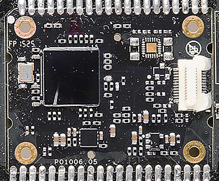
Top of a P01006.05 board soldered on P3X:
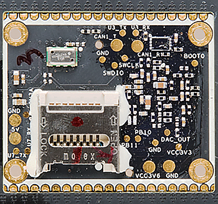
Bottom of the P01006.05 board soldered on P3X:
Top of a P01006.05 board soldered on P3C:

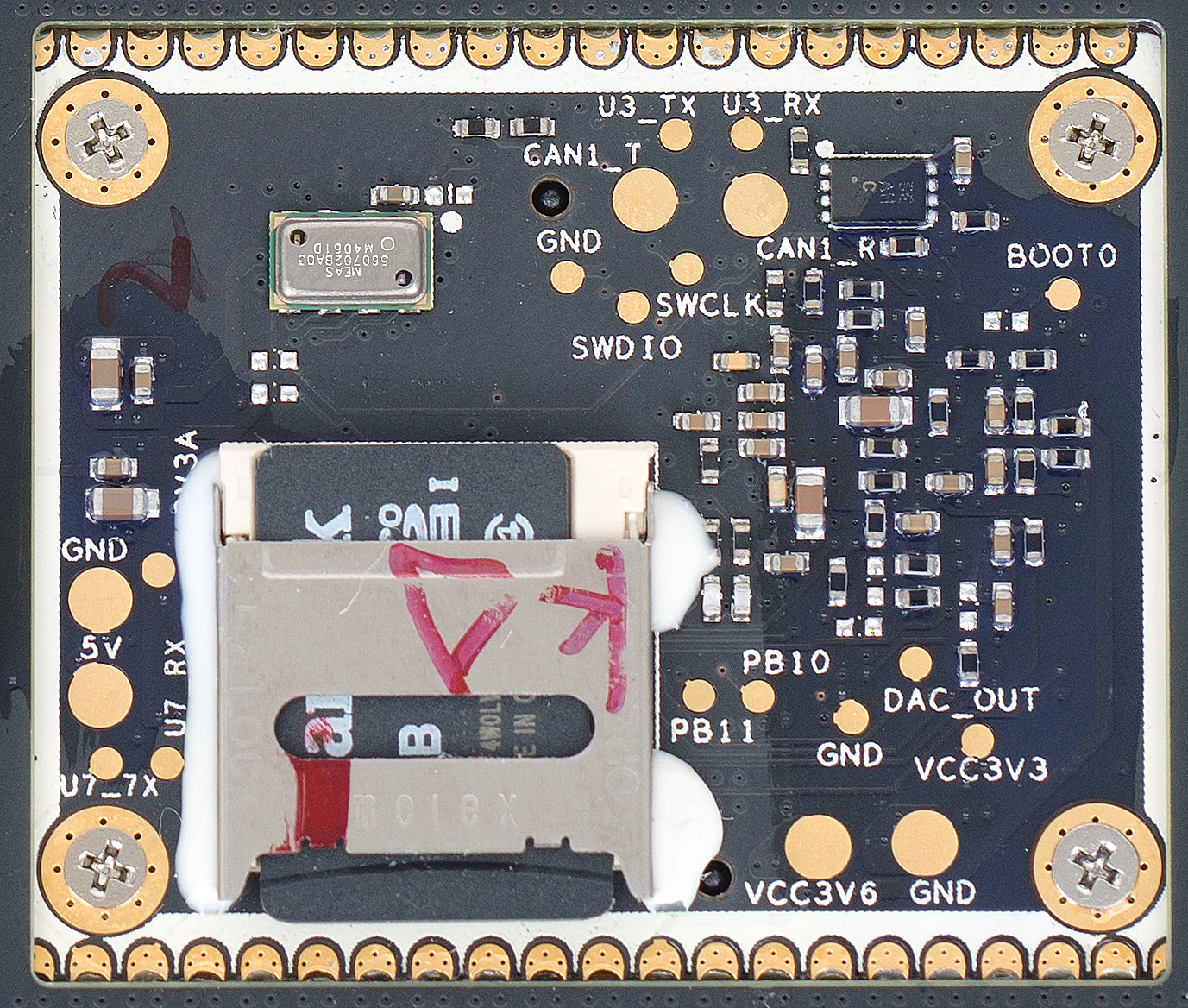
Bottom of the P01006.05 board soldered on P3C:
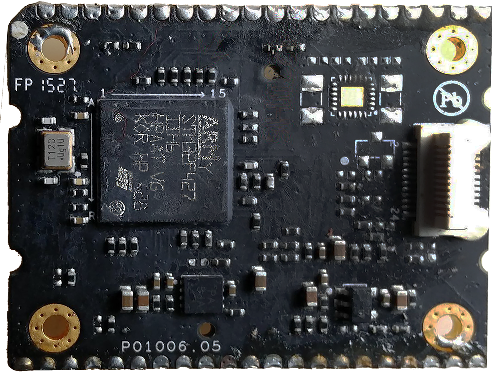
Top of a P01006.05 board with black resin scrubbed out:
Top of a second P01006.05 board with black resin removed:

IMU board above a P01006.05 board soldered on P3C:

Another IMU board board from P3C:

The following schematics were made by enthusiasts: