10. VehicleLoadingModel
ST loads vehicles according to the loading model in MITSIMLab. Originally, MITSIMLab loads the vehicle based on their lane selection and speed assignment components (Yang et al., 2000), however Burghout and Koutsopoulos (2008) pointed out the turbulence issue while loading and proposed new loading model with modified speed assignment method.
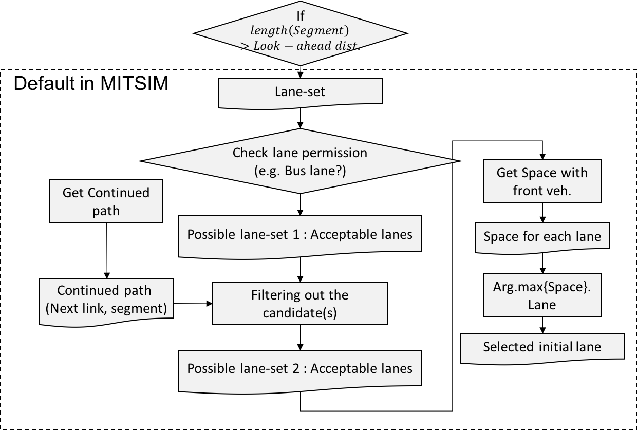
ST loads vehicles uniformly at the source node if the link is composed by multiple segments. However, if the first segment length is less than the driver’s look-ahead distance, ST assigns the designated lane to the driver with the lane selection process. To select the initial lane, among the set of lanes (Lane-set), ST checks the lane permission to list up the acceptable lanes (Possible lane-set 1). With the continued path of driver, ST filtering out the second acceptable lanes (Possible lane-set 2). Of the possible lane-set 2, ST calculates the spacing with driver’s leader vehicle in each lane, and finally assign the lane with most space as the initial lane.
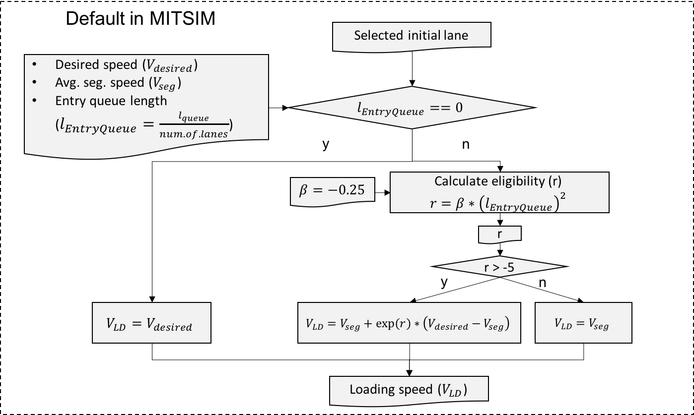
Once ST assign the initial lane to the driver, loading speed is calculated based on the desired speed, average segment speed, and entry queue length. It the entry queue length is 0, the vehicle start his trip with desired speed. Otherwise, his loading speed will be determined as average segment speed. According to the MITSIMLab manual (2002), MITSIMLab code calculates the entry speed with the average speed on the link, desired speed, and coefficient for queue. It first calculate the eligibility (r) with the coefficient for queue (Beta, set as -0.25). If the eligibility (r) is less than -5, the loading speed will be calculated somewhere between the average segment speed and desired speed. Otherwise, the loading speed will be assigned with the average segment speed.
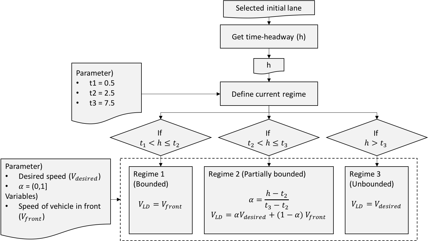
Burghout and Koutsopoulos (2008) proposed a improved speed assignment model to be consistent with real driving behavior. Based on the multi-regime approach with time-headway with driver and his leader (h), ST classifies the driver’s regime into three categories with time headway threshold as:
- Regime 1 (bounded traffic): t1<h<=t2
- Regime 2 (Partially bounded traffic): t2<h<=t3
- Regime 3 (Unbounded traffic): h>t3
According to the literature (Burghout and Koutsopoulos, 2008), the headway threshold for speed assignment model had been estimated with real data collected from E4 motorway (Essingeleden in Stockholm) through the consecutive vehicle speed correlation analysis.
- T1 = 4m (minimum headway parameter)
- T2 = 14m
- T3 = 40m
These spacing headway thresholds are needed to be tuned over calibration process. The suggested thresholds by Burghout and Koutsopoulos (2008) are: T1 = 0.5 sec, T2 = 2.5 sec, T3 = 7.5 sec.
- Burghout and Koutsopoulos (2008) Hybrid Traffic Simulation Models: Vehicle loading at meso-micro boundaries (http://kth.diva-portal.org/smash/record.jsf?pid=diva2%3A227753&dswid=1267)
- Yang, Q., Koutsopoulos, H., & Ben-Akiva, M. (2000). Simulation laboratory for evaluating dynamic traffic management systems. Transportation Research Record: Journal of the Transportation Research Board, (1710), 122-130.
- MIT ITS (2002) User guide for MITSIMLab and RNE