5.2 AccelerationRegimesDescription
The maximum acceleration is defined by function maxAcceleration() and represents the initial limiting acceleration value.
This function uses the grade, the current speed of vehicle, the vehicle type and a set of predefined parameters in the parameter XML file (see Section 5.4):

where the maxTableAcc is a table (predefined in the parameter XML configuration file, see Section 5.4) with values depending on the current speed and the vehicle type; g is the grade (in %), beta_grade is the predefined (XML config file) grade factor, and beta_acc is a random multiplier given by a predefined distribution (also specified in the XML config file).
In MITSIM the equivalent maximum acceleration function is maxAcceleration in the TS_VehicleLib file. In MITSIM parameter Paralib.dat file, these three structures are defined for keeping the predefined parameters needed for this and other functions.
"In the merging area, additional constraints are considered in calculating acceleration rate because vehicles from adjacent upstream lanes may need to coordinate with each other. For the purposes of the simulator, merging is classified into: i) Priority merging, includes merging from ramps to freeways, and from minor streets to major streets. ii) Non-priority merging, occurs at the downstream of toll plazas, and lane drops on freeways.
For priority merging, a vehicle without right-of-way must check whether there is any vehicle from the competing upstream lanes. The vehicle executes the merge only if the projected headway gap is acceptable. If the headway gap is not acceptable, the vehicle either calculates the car-following acceleration rate by treating the vehicle which has the right-og-way as leader or it prepares to stop at the end of the lane depending on which case is the critical one.
For non priority merging, a "First come, first serve" principle determines right-of-way. In other words, among all the vehicles coming from competing upstream lanes, the one closet to the downstream lane is chosen as the first vehicle to merge. Other vehicles will either following appropriate leaders or prepare to stop at the end of their current lanes. However, freeways and on ramps have different priority, and separate procedures are applied.
The acceleration in merging areas is defined by aB and given by function calcMergingRate.

Flow chart for calcMergingRate
The acceleration accMerg1 is given by:
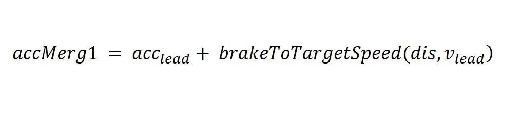
where acc_lead and v_lead is the acceleration and speed of the lead vehicle in the next lane (both vehicles in freeway type lane).
The calcMergingRate also uses the auxiliary function isInMergingArea() defined in Section 5.3, which defines if a vehicle should be tagged as a merging vehicle. distanceToNormalStopis the distance required to brake to a stop with the normal deceleration rate at current speed. A vehicle will not decelerate unless its distance from event is less than the distance computed in this function. vehicleAheadInTypedLanes and vehicleBehindInTypedLanes are auxiliary functions that find the lead and lag vehicles, respectively, in the lanes connected to the next lane. In MITSIM, these auxiliary functions are specified in TS_Vehicle.cc. brakeToStop and brakeToTargetSpeed are defined in Section 5.3.
It is worth to note that if a vehicle is constrained by a front vehicle in the same lane, the car-following regime might be the relevant one. This checked by function calcCarFollowingRate (different from carFollowingRate, as specified in Section 5.3.
Another component considered in the acceleration decision is the acceleration rate when the car is stopped at a traffic light, aC and it is defined by the function calcSignalRate. The logic of the calculation of this acceleration follows the rules as:
The acceleration accMerg1 is given by:

Flow chart for calcSignalRate
When a vehicle is within the visibility range computed considering the visibility of the driver and of the traffic signal itself, its acceleration will depend on the color of the signal.
- If the signal is red, the deceleration will be given by
brakeToStop - If the signal is yellow, the function
brakeToStopis also used, but only if the distance to stop divided by the maximum between the vehicles current speed and a predefined minimum speed with yellow (in the XML file) is greater than a predefinedyellowStopHeadwaydistance - If green, the function outputs the maximum acceleration
The function calcYieldingRate calculates the acceleration rate when performing a courtesy yielding, aD. This function uses carFollowingRate with the vehicle on the target lane as the nearest vehicle, either on the left or the right lane. It further uses calcCreateGapRate when a vehicle is nosing, the rate subject to the gap from the leading vehicle.
This function checks two cases:
- If the vehicle is yielding to another vehicle, it follows that vehicle and subjects to normal deceleration rate
- If the vehicle is nosing, it follows the leader of the yielding vehicle It may also cancel the yielding or nosing state if they becomes invalid.
This function is based on a set of verification considering the yielding and nosing "Flags", which, similarly to the STATUS variable, aim at internal use, debugging and visualization. The flags for the yielding and nosing state are assigned in the lane-changing model (see Section 6.1)
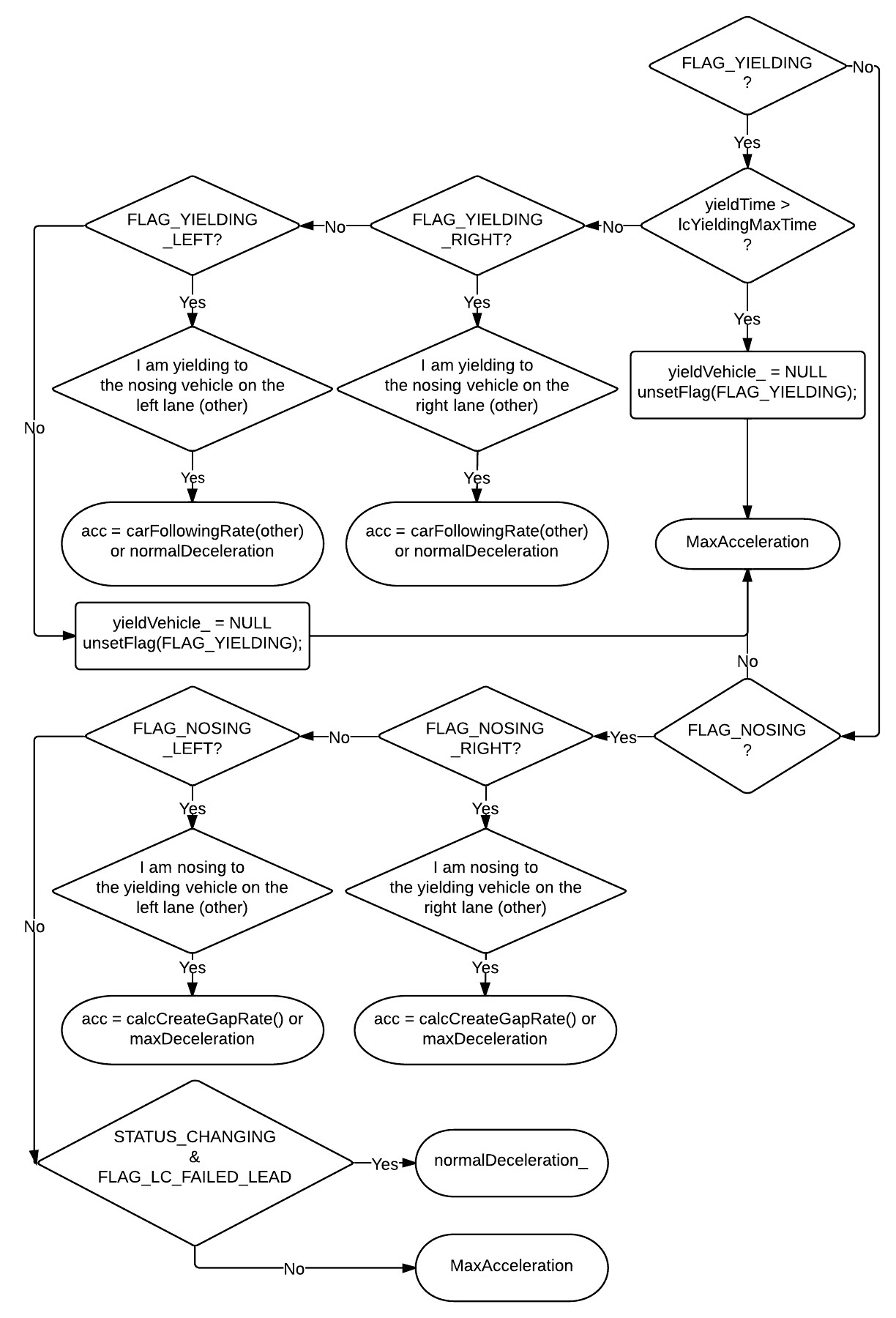
Flow chart for calcYieldingRate
The function waitExitLaneRate calculates the acceleration rate before exiting a specific lane, aE. If a vehicle is not in the correct lane leading to its destination close to the end of a link, it may decelerate to a stop and wait for lane-changing.
Flow chart for waitExitLaneRate
The distanceToNormalStop and brakeToStop functions are defined in Section 5.4. This function is based on a set of verifications considering the yielding and nosing "Flags" and the STATUS variable. These are assigned in the lane-changing model as in Section 6.1.
If current lane is incorrect and the distance is close to an incurrent lane of the segment, the vehicle decelerates to a stop and wait for lane-changing. This behavior is modeled with waitAllowedLaneRate function and represented by aF in the acceleration choice decision.
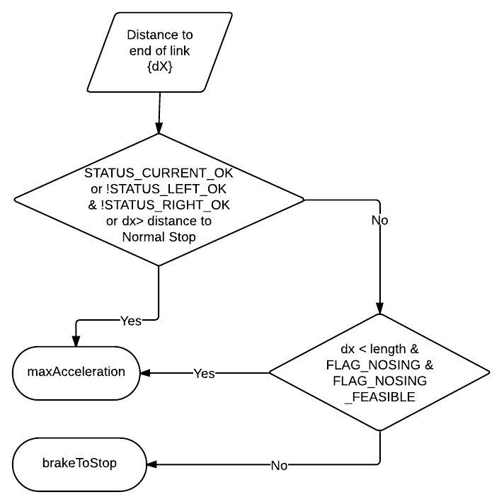
In the Flowchart below, dx is the distance to segment end and dstop is calculated by distanceToNormalStop (see Section 5.3). The brakeToStop acceleration is defined in section Section 5.4. In MITSIM, the equivalent acceleration ig given by TS_Vehicle::waitAllowedLaneRate(). This function is based on a verification considering the yielding and nosing "Flags". This flag is assigned in the lane-changing model (Section 6.1).

Flow chart for waitAllowedLaneRate
If next lane is !NULL, then stop and wait for merging into mainstream. This behavior is modeled with calcLaneDropRate function and represented by aG in the acceleration choice decision.

Flow chart for calcLaneDropRate
The breakToStop acceleration is defined in AccelerationParameterDefinition. In MITSIM, the similar function is given by TS_Vehicle::calcLaneDropRate().
The target gap acceleration model captures the behavior of drivers who target a lane-change and follow a short-term plan to accomplish it. Drivers are assumed to modify their acceleration behavior to facilitate completing their short-term plan. Acceleration models for the 3 alternative target gaps (the forward, backward and adjacent gaps) are estimated.
Here the driver may be in a constrained regime, in which it is affected by the vehicle in front, or in an unconstrained regime. In the constrained regime, the driver is assumed to focus on the stimulus created by its leader and apply car-following behavior. In the unconstrained regime, rather than applying a free-flow acceleration, the driver chooses an acceleration that enables reaching the gap.
A set of three different accelerations are now specified for the target gap acceleration aH:
-
calcForwardRatecalculates the acceleration for the forward gap. -
calcBackwardRatecalculates the acceleration for the backward gap. -
calcAdjacentRatecalculates the acceleration for the adjacent gap.
This model describes the behavior of drivers whose short-term plan is to use the forward gap to change to the target lane.

Target gap acceleration
The subject vehicle (vehicle A) is committed to changing to the left lane using the forward gap, the gap between vehicles B and C. The acceleration of this vehicle depends on its relations with the vehicle in front of it in the current lane (vehicle D) and the vehicles defining the forward gap in the target lane (vehicles B and C). All three gap acceleration functions are based on the same logic:
calcBackwardRatecalcAdjacentRate.jpg)
calcForwardRate, calcBackwardRate, and calcAdjacentRate
where TL is the target lane and gap is either forward, backward or adjacent.
Both forward and backward gap acceleration functions use the same generic:

where, DeltaV_plus and DeltaV_minus are the positive negative relative target lane leader speeds, respectively.