-
Notifications
You must be signed in to change notification settings - Fork 5
Dreamer_Nano_V4.0_(DFR0213)

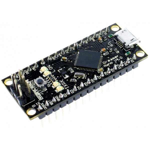
The Dreamer Nano V4.0 is a surface mount breadboard embedded version of the ATMEGA 32U4 with integrated Micro USB. It has everything that Leonardo has (electrically).Physically, it is just missing power jack to save space.
Using the ATmega32U4 as its sole microcontroller allows it to be cheaper and simpler. Also, because the 32U4 is handling the USB directly, code libraries are available which allow the board to emulate a computer keyboard, mouse, and more using the USB-HID protocol!
The Dreamer Nano v4.0 is compatible with most Nano shield in the market. It's suitable for projects that require a compact size controller system.
- Microcontroller:ATmega32u4
- Operating Voltage:5V
- Input Voltage (recommended):6.5-12v (VIN) / 5v (Micro USB)
- Input Voltage (limits):6-12V
- Digital I/O Pins:20
- PWM Channels:7
- Analog Input Channels:12
- DC Current per I/O Pin:40 mA
- DC Current for 3.3V Pin:50 mA
- Flash Memory:32 KB (ATmega32u4) of which 4 KB used by bootloader
- SRAM:2.5 KB (ATmega32u4)
- EEPROM:1 KB (ATmega32u4)
- Clock Speed:16 MHz
- Compatible with most of Nano shield
- Size: 45x20x20mm
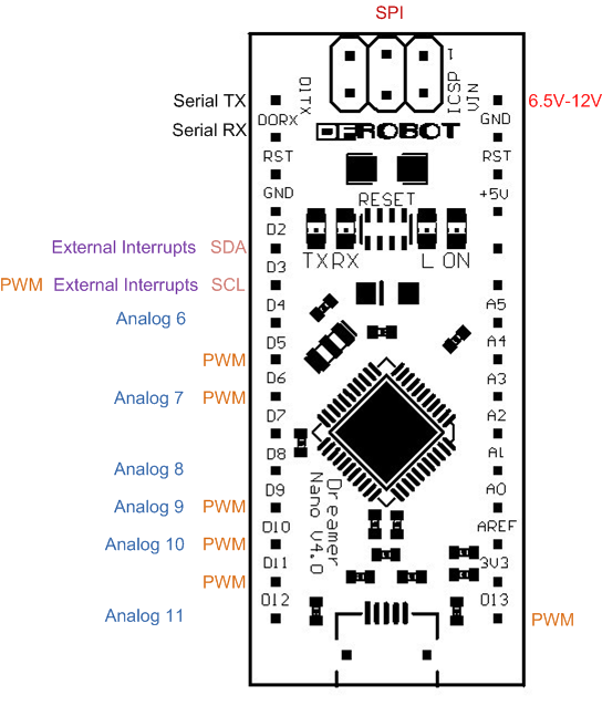
Each of the 20 digital i/o pins on the Uno can be used as an input or output, using pinMode(), digitalWrite(), and digitalRead() functions. They operate at 5 volts. Each pin can provide or receive a maximum of 40 mA and has an internal pull-up resistor (disconnected by default) of 20-50 kOhms. In addition, some pins have specialized functions:
- Serial: 0 (RX) and 1 (TX). Used to receive (RX) and transmit (TX) TTL serial data using the ATmega32U4 hardware serial capability. Note that on the Leonardo, the Serial class refers to USB (CDC) communication; for TTL serial on pins 0 and 1, use the Serial1 class.
- TWI: 2 (SDA) and 3 (SCL). Support TWI communication using the Wire library.
- External Interrupts: 2 and 3. These pins can be configured to trigger an interrupt on a low value, a rising or falling edge, or a change in value. See the attachInterrupt() function for details.
- PWM: 3, 5, 6, 9, 10, 11, and 13. Provide 8-bit PWM output with the analogWrite() function.
- SPI: on the ICSP header. These pins support SPI communication using the SPI library. Note that the SPI pins are not connected to any of the digital I/O pins as they are on the Uno, They are only available on the ICSP connector. This means that if you have a shield that uses SPI, but does NOT have a 6-pin ICSP connector that connects to the Leonardo's 6-pin ICSP header, the shield will not work.
- LED: 13. There is a built-in LED connected to digital pin 13. When the pin is HIGH value, the LED is on, when the pin is LOW, it's off.
- Analog Inputs: A0-A5, A6 - A11 (on digital pins 4, 6, 8, 9, 10, and 12). The Leonardo has 12 analog inputs, labeled A0 through A11, all of which can also be used as digital i/o. Pins A0-A5 appear in the same locations as on the Uno; inputs A6-A11 are on digital i/o pins 4, 6, 8, 9, 10, and 12 respectively. Each analog input provide 10 bits of resolution (i.e. 1024 different values). By default the analog inputs measure from ground to 5 volts, though is it possible to change the upper end of their range using the AREF pin and the analogReference() function.
There are a couple of other pins on the board:
- AREF. Reference voltage for the analog inputs. Used with analogReference().
- Reset. Bring this line LOW to reset the microcontroller. Typically used to add a reset button to shields which block the one on the board.

The Dreamer Nano can be programmed with the official Arduino software (download). Select "Arduino Leonardo from the Tools > Board menu (according to the microcontroller on your board).
The ATmega32U4 on the Dreamer Nano comes preburned with a bootloader that allows you to upload new code to it without the use of an external hardware programmer. It communicates using the AVR109 protocol. You can also bypass the bootloader and program the microcontroller through the ICSP (In-Circuit Serial Programming) header; see these instructions for details.