URM07_I2C_Ultrasonic_Sensor_(SKU_SEN0166)
The URM07 Series is DFRobot's new ultrasonic range sensor, which uses integrated ultrasonic probe, and has features of compact size and excellent environmental adaptability. Comparing with general ultrasonic sensors which determine range through returning signal strength, the URM07 Series uses algorithms to collect multiple signals and runs signal analysis. As a result, the URM07 Series is able to detect high-absorbent objects.
Whatsmore, the URM07 series is also equipped with temperature compensation, which is achieved by measuring the ambient temperature on the amount of compensation and to get more accurate range results.
- Operating Voltage: DC 5V ~ 8V
- Operating Temperature : -10 ℃ ~ 70 ℃
- Operating Current : <= 15mA
- Ultrasonic Frequency: 40 KHz
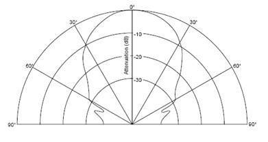
- Detecting Angle: 60 °
- Detecting Distance: 100mm ~ 5000mm
- Measuring Error: 1%
- Measuring Resolution: 1mm
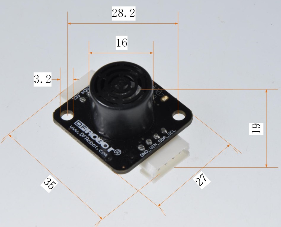
- Dimensions: 27mm x 35mm x 19mm
- High adaptability to a variety of obstacles
- Built-in temperature compensation
- Power supply reverse polarity protection
- Over-current protection
- Can be cascaded
- Module Size

- Supporting cable length: 15-16cm
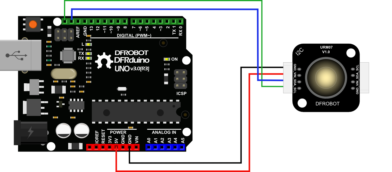
- I2C:4 pins and 2.54mm pintch, has two directly connected I2C interfaces, multiple modules can be cascaded to use.
-
- GND: positive power supply
-
- VIN: negative power supply
-
- SDA: Serial data Line
-
- SCL: Serial clock line
- Indicator: On when power ready, off when module is ready; On when the module and the host are communicating, off when communication off.

See detailedPB00005-DFRobot I2C protocol V1.0.
There are 15 registers at the module. The module can be controlled by its registers that can be written(W) or read(R) by Master. These registers are defined as follow:
| align = "center" | Register Address | align = "center" | Write/Read | align = "center" | Function | align = "center" | Default Value | |-------------------------------------|-------------------------------|---------------------------------------------------------------------------------------|------------------------------------------------------| | align = "center" | 0 | align = "center" | R | align = "left" | Version of I2C library | align = "center" | | | align = "center" | 1 | align = "center" | R | align = "left" | Module Type | align = "center" | 4 (Ultrasonic) | | align = "center" | 2 | align = "center" | R | align = "left" | Module Serials | align = "center" | 1 (URM) | | align = "center" | 3 | align = "center" | R | align = "left" | Module sub-Serials | align = "center" | 7 | | align = "center" | 4 | align = "center" | R | align = "left" | Hardware Version | align = "center" | | | align = "center" | 5 | align = "center" | R | align = "left" | Software Version | align = "center" | | | align = "center" | 6 | align = "center" | R/W | align = "left" | Control Byte:
                                                                   0xee=save these registers value to EEPROM,and then the module restart

                                                                   0xfc=restore default value of registers

                                                                   0xff=trigger once ranging in Manual Trigger Mode                                       | align = "center" |                                   |
| align = "center" | 7 | align = "center" | R/W | align = "left" | Pullup resistor of I2C bus: 0=Disable, 1=Enable | align = "center" | 0 |
| align = "center" | 8 | align = "center" | R/W | align = "left" | Slave Address, 1126 (0 is broadcast address, 127 is Master address) | align = "center" | 0x11(17) |
| align = "center" | 9 | align = "center" | R/W | align = "left" | Ranging Trigger Mode: 0=Manual, 1=Auto | align = "center" | 0 |
| align = "center" | 10 | align = "center" | R/W | align = "left" | Cycle in Auto trigger mode: 3254, unit=10ms | align = "center" | 0 (Continue, Cycle is about 30ms) |
| align = "center" | 11 | align = "center" | R/W | align = "left" | Ranging Unit: 0=cm,1=mm,2=inch,3=microsecond | align = "center" | 0 |
| align = "center" | 12 | align = "center" | R | align = "left" | Temperature,it is Signed char type, unit=Celsius | align = "center" | |
| align = "center" | 13 | align = "center" | R | align = "left" | High byte of distance | align = "center" | |
| align = "center" | 14 | align = "center" | R | align = "left" | Low byte of distance | align = "center" | |
Note:The new value of writable register will lost after power down until save them to EEPROM.
URM module and the control module is connected via supporting cable or DuPont cable. Any I2C interface can be used.


- In the cascade mode, the module cannot be the same address.
- Get distance: See sample URM_I2C_measure.
- Get temperature: See sample URM_I2C_measure.
- Set address: See sample URM_I2C_set. When multiple modules to be cascaded are same address or unknown, please first connect module by individual way and set the corresponding address. For the convenience of the late identification, proposal paste the address label on the module.
- Set unit of distance: See sample URM_I2C_set.
Example link:[ https://github.com/DFRobot/DFI2C DFRobot_I2C library and samples].
- The module itself is not waterproof.
- Do not keep long in dusty, highly humid environment.
- If there are same or similar frequency ultrasounds emitting at the same time in the same space, it will affect the measurement results.
- Do not support Hot Plugging-in.