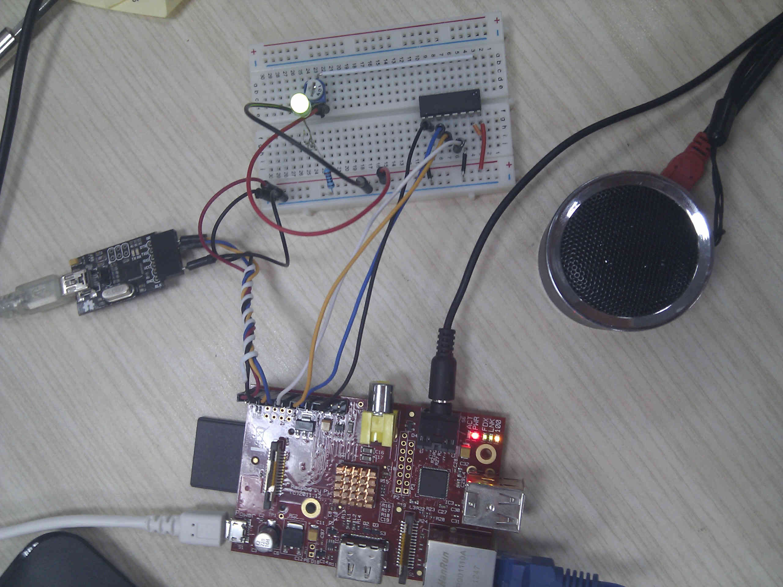
Rpi_analog_sensors
This tutorial will help you get start with Rpi and analog sensors. You need a working Raspberry Pi, connected to the network. You will use python, and Analog to Digital Converter (ADC).
This tutorial assumes your Raspberry Pi is using raspbian OS, and is connected to the network. If you Didn't do this steps, please check the following links:
Download your raspbian image: http://www.raspberrypi.org/downloads
To set up your SD card: http://elinux.org/RPi_Easy_SD_Card_Setup
To Connect to your RPi: http://elinux.org/RPi_Serial_Connection ( check the pinout picture below for wiring help )
Power supply: 3.3v Pin definition: 1-Analog output(Blue wire) to the analog channel on MCP3008 2-GND(Black wire) 3-Power(Red wire)
Moisture sensor(1 unit) Analog Sensor Cable (1 unit)
 added a LED on the analog pin, to check the voltage level so I can discard other possible problems while running my code and if it does not work

Download and install the required packages
sudo apt-get install python-dev python-setuptools alsa-utils mpg321 vim
Then run this command:
sudo easy_install rpi.gpio
This will help you get the raspberry Pi Gpio libraries.
Open up vim (or your favourite text editor for linux) and copy the python code below. Make the file executable and run it with python.
chmod +x analog_read_example.py
Before you run this example, you have to start some sound:
mpg321 ./../theme-song-super-mario.mp3 &
Use & at the end of your command to make it run in the background if you are logged in on the serial port.
#!/usr/bin/env python
import time
import os
import RPi.GPIO as GPIO

GPIO.setmode(GPIO.BCM)
DEBUG = 1

# read SPI data from MCP3008 chip, 8 possible adc's (0 thru 7)
def readadc(adcnum, clockpin, mosipin, misopin, cspin):
        if ((adcnum > 7) or (adcnum < 0)):
                return -1
        GPIO.output(cspin, True)

        GPIO.output(clockpin, False)  # start clock low
        GPIO.output(cspin, False)     # bring CS low

        commandout = adcnum
        commandout |= 0x18  # start bit + single-ended bit
        commandout <<= 3    # we only need to send 5 bits here
        for i in range(5):
                if (commandout & 0x80):
                        GPIO.output(mosipin, True)
                else:
                        GPIO.output(mosipin, False)
                commandout <<= 1
                GPIO.output(clockpin, True)
                GPIO.output(clockpin, False)

        adcout = 0
        # read in one empty bit, one null bit and 10 ADC bits
        for i in range(12):
                GPIO.output(clockpin, True)
                GPIO.output(clockpin, False)
                adcout <<= 1
                if (GPIO.input(misopin)):
                        adcout |= 0x1

        GPIO.output(cspin, True)

        adcout >>= 1       # first bit is 'null' so drop it
        return adcout

# change these as desired
SPICLK = 18
SPIMISO = 23
SPIMOSI = 24
SPICS = 25

# set up the SPI interface pins
GPIO.setup(SPIMOSI, GPIO.OUT)
GPIO.setup(SPIMISO, GPIO.IN)
GPIO.setup(SPICLK, GPIO.OUT)
GPIO.setup(SPICS, GPIO.OUT)

# 10k trim pot connected to adc #0
potentiometer_adc = 0;

last_read = 0       # this keeps track of the last potentiometer value
tolerance = 5       # to keep from being jittery we'll only change
                    # volume when the pot has moved more than 5 'counts'

while True:
        # we'll assume that the pot didn't move
        trim_pot_changed = False

        # read the analog pin
        trim_pot = readadc(potentiometer_adc, SPICLK, SPIMOSI, SPIMISO, SPICS)
        # how much has it changed since the last read?
        pot_adjust = abs(trim_pot - last_read)

        if DEBUG:
                print "trim_pot:", trim_pot
                print "pot_adjust:", pot_adjust
                print "last_read", last_read

        if ( pot_adjust > tolerance ):
               trim_pot_changed = True

        if DEBUG:
                print "trim_pot_changed", trim_pot_changed

        if ( trim_pot_changed ):
                set_volume = trim_pot / 10.24           # convert 10bit adc0 (0-1024) trim pot read into 0-100 volume level
                set_volume = round(set_volume)          # round out decimal value
                set_volume = int(set_volume)            # cast volume as integer

                print 'Volume = {volume}%' .format(volume = set_volume)
                set_vol_cmd = 'sudo amixer cset numid=1 -- {volume}% > /dev/null' .format(volume = set_volume)
                os.system(set_vol_cmd)  # set volume

                if DEBUG:
                        print "set_volume", set_volume
                        print "tri_pot_changed", set_volume

                # save the potentiometer reading for the next loop
                last_read = trim_pot

        # hang out and do nothing for a half second
        time.sleep(0.5)
Shopping [none Sensor ]
category: Product Manual category: DFR Series category: Sensors category:source category:Diagram