HCR Mobile_robot_platform_V2.0_(SKU_Unknow)
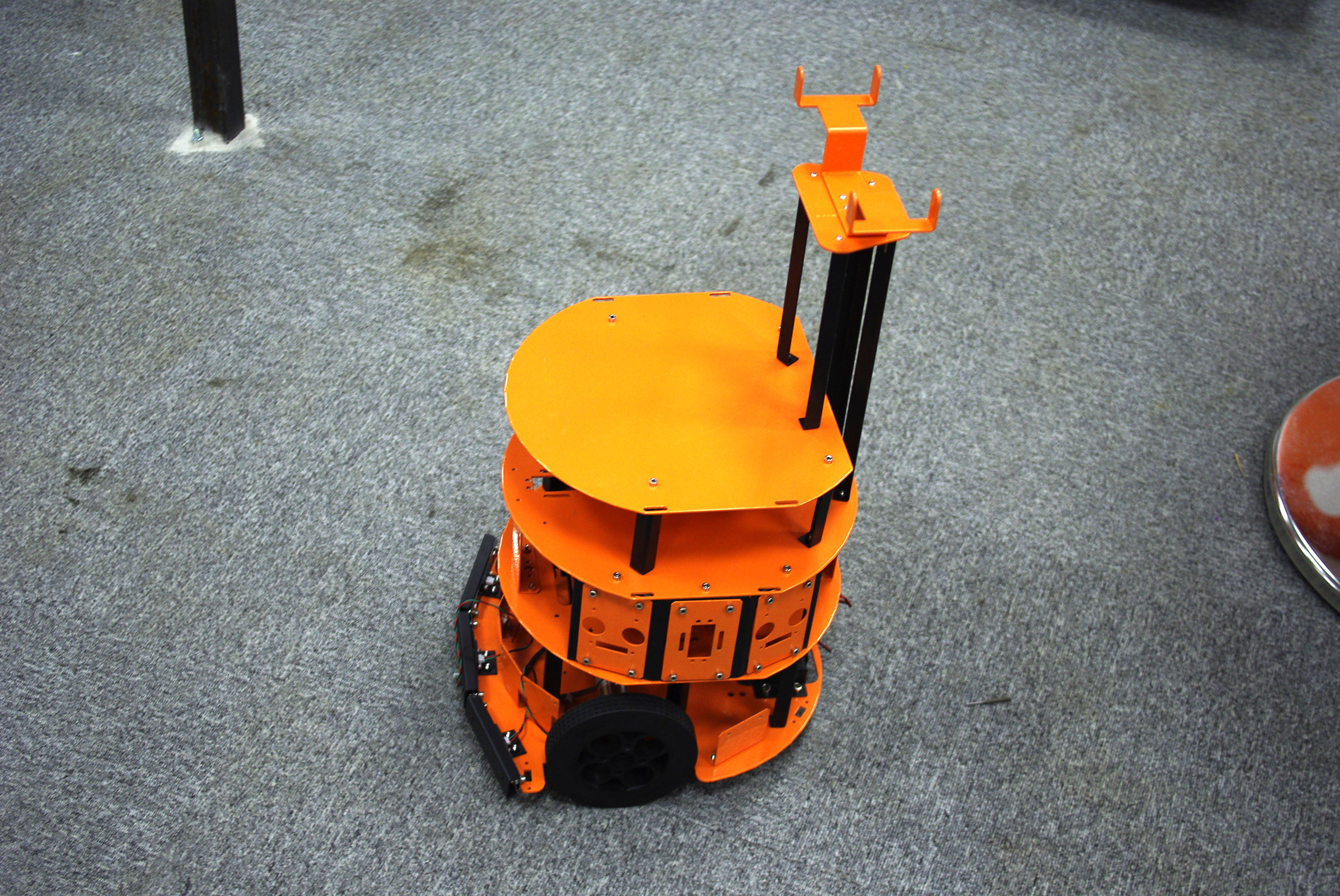 the hcr mobile robot kit is a two wheel drive mobile robot platform which has three levels included (if you want, you can use only the parts you need, or make a two level robot). the kit includes two motors, 2 wheels (and one rotating third wheel) and all associated plates and hardware. the supports include spaces for servos and sensors and the base has holes specifically for mini-its motherboards. this is a second release of the hcr. in this update, new motors and new wheels have been updated. the composition of the sensors is changed. now, there are 6 urm sensors in 6 different directions. and about the new motor, this is dfrobot customized high quality dc motor. the best part of this motor is that it is a quiet and high torque output motor with optical encoder building. the optical encoder gives 663 pulse per rotation which is able to sensor 0.54 degree rotation from the shaft. the resolution can meet a general pid speed control requirements. a new level for users to do more interesting things. like a Kinect for XBOX 360.
- Aluminum power-coated orange
- Associated plates and hardware
- 30X30X35cm
- Motor: 51:1 Gearbox 8000 rpm
- 3 levels
- Wheels: diameter 13cm
- Main controller: Arduino Mega ADK/2560
- Motor controller: Arduino Nano
- URM driver: Arduino Nano
- Motor driver: DC Motor Driver 2×15A – Lite/ Sabertooth dual 12A motor driver
- Two DC motors with 51:1 Gearbox 8000 rpm
- Two encoders with 13 PPR
- 2 wheels (and one caster wheel)
- Three bumper sensors
- Five Sharp GP2D12 infrared sensors
- Six URM04http://d25s4dbsms5nvt.cloudfront.net/img/srdn/icon-64.png v2.0 Ultrasonic Sensors


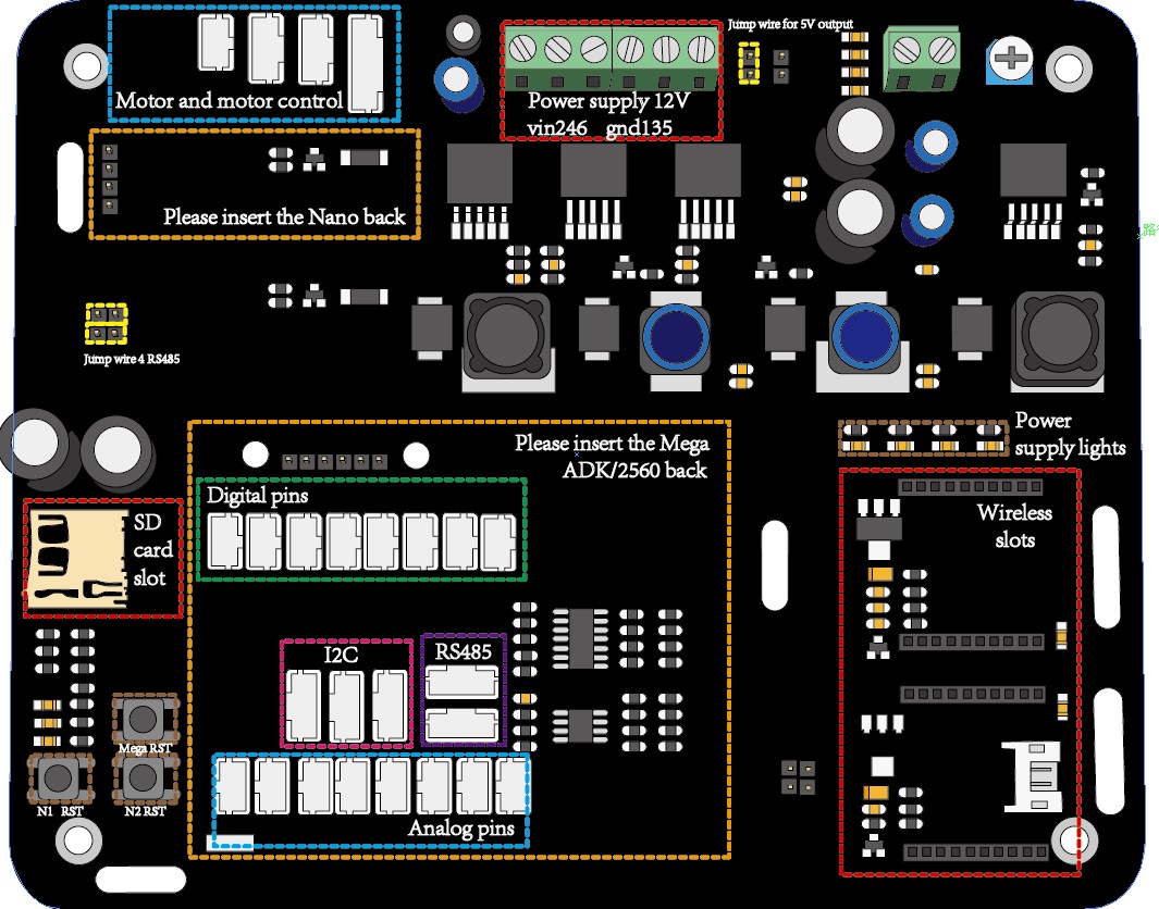
Attention: The yellow wires are jump wires.
And for this GMR board 3 microcontrollers should be used. Two Arduino Nano and one Arduino Mega ADK. One of Nano to control the motors and the other used to drive 6 URM sensors. And the Main microcontroller is the Mage ADK, it is used to collect the date and transfer it. There are two Wireless slots for Xbee, blueteeth and other wireless communications. In this case, we just need one Nano to drive the motors.
- Insert the Mega and Nano on the GMR board, see Picture3 and connect the output of the switch system to the power supply of the motor controller and the GMR board.
- Turn off the switch.
- Connect the circuits as the connection diagram (Pictutre2), connect two motors, the motor controller we will test it first
- Use the example code of the motor control which have been listed in software architecture.
- Test the speed and the direction of the motor. Make sure the motor will run suit your need.
- Connect the bumpers and IR sensor, the example codes also have been listed. You may test it use another microcontroller (Arduino Uno), then move the codes to the Mega ADK
- The codes of the motor control should be used in Nano and the codes of the bumpers and IR sensors should be used in Mega ADK. The communication between Nano and Mega ADK is I2C.
- After testing the codes you can follow the guide and make the HCR move.
- Assemble the HCR First, see the assembly guide.
- Remove the 3rd level and the 2nd level of the HCR.
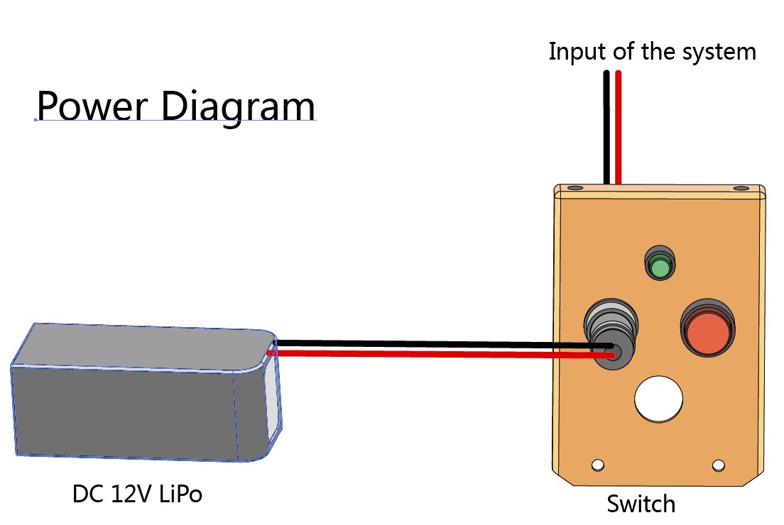
- Fix the Battery in the 1st level, connect the switch system as Picture4, and fix the 2nd level again.
- Insert the Mega and Nano on the GMR board and put the GMR board in 2nd level and fix it, see Picture3 and connect the output of the switch system to the power supply of the motor controller and the GMR board.
- Connect the circuits as the connection diagram (Pictutre2), include two motors, the motor controller, 3 bumpers and 7 IR sensors. And the motor controller can be fixed with the GMR board.
- According to your choice, upload the code to the Mega and Nano. The example code have been listed in software architecture. And the communication between the Nano and Mega is I2C. And the code on the Nano (motor control) can drive the wheels.
- Fix the 3rd level again.
In this part, the example code of the HCR will be listed, It is written by Arduino, include the motor control, bumper and the IR sensor.
The code can only be used by IDE over 1.0
Code on Arduino Nano control the motor: If use the Sabertooth motor control, the motor can be control by <serve.h> perfect.
- Code:
#include <Servo.h>
Servo Lmotor;
Servo Rmotor;
float Lspeed = 0; //from 0-180, 0 means max speed forwards, 180 means max speed backwards 90 means stop
float Rspeed = 0; //from 0-180,

void setup()
{
  Lmotor.attach( 9, 1000, 2000);
  Rmotor.attach( 10, 1000, 2000);
}

void loop()
{
   Lmotor.write(Lspeed);
   Rmotor.write(Rspeed);
   delay(500);
} // use this code to control the HCR move
If use the DC Motor Driver 2×15A – Lite
- Code:
#define LF 0
#define RT 1
int E1 = 9;     //M1 Speed Control
int E2 = 10;     //M2 Speed Control
int M1 = 8;     //M1 Direction Control
int M2 = 11;     //M1 Direction Control
int a;
int b;
int counter=0;

void setup()
{
  int i;
  for(i=4;i<=7;i++)
  pinMode(i, OUTPUT);
  Serial.begin(57600);      //Set Baud Rate
  Serial.println("Run keyboard control");
  digitalWrite(E1,LOW);
  digitalWrite(E2,LOW);
}

void loop()
{
  Motor(2000,LF);
  Motor(1000,RT);
}

void Motor(int value,byte whichwheel)
{
  value = constrain(value,1000,2000);
  if(whichwheel == LF) {
    if(value>1500) {
      a=(value-1500)/1.961;
      analogWrite (E1,a);
      digitalWrite(M1,HIGH);
    }
    else {
      a=(1500-value)/2;
      analogWrite (E1,a);
      digitalWrite(M1,LOW);
    }
  }
  else if(whichwheel == RT){
    if(value>1500) {
      b=(value-1500)/1.961;
      analogWrite (E2,b);
      digitalWrite(M2,HIGH);
    }
    else {
      b=(1500-value)/2;
      analogWrite (E2,b);
      digitalWrite(M2,LOW);
    }
  }
}
The first thing is make the wheels move
- Code of the bumper:
BumperFunction.h
#include "Arduino.h"

int BumperR_pin;
int BumperL_pin;
int BumperC_pin;
byte BumperValue;
boolean blocked = false;
void OpenBumper(int,int,int);
void bumperRead();
/*************************** Details *****************************/


void OpenBumper(int LIO,int CIO,int RIO)
{
  BumperL_pin = LIO;
  BumperC_pin = CIO;
  BumperR_pin = RIO;

  pinMode(BumperL_pin,INPUT);
  pinMode(BumperC_pin,INPUT);
  pinMode(BumperR_pin,INPUT);
}
/*************************************************Bumper Sensor Status***********************************/
void bumperRead()
{
  BumperValue = 0x07;
  BumperValue=digitalRead(BumperL_pin)<<2;
  BumperValue|=digitalRead(BumperC_pin)<<1;
  BumperValue|=digitalRead(BumperR_pin);
//  Serial.println(BumperValue,BIN);
}
Code of the IR sensor:
/********************** IR sensor ***********************/
void IRreader()//detect distance on both sides
{
  static float IRdata[IrNumber] = {
    80,80,80,80,80                  };
  for(int h=0;h<IrNumber-2;h++)
  {
    float volts = analogRead(h + 1);
    _iR[h] = (6787 / (volts - 3)) - 4;
    if(_iR[h]<10)   _iR[h] = 80;
    _iR[h] = min(_iR[h],80);
    _iR[h] = max(_iR[h],12);
  }
    for(int h=5;h<7;h++)
    {
      float volts = analogRead(h-4);
      _iR[h] = (6787 / (volts - 3)) - 4;
      if(_iR[h]<10) _iR[h] = 80;
      _iR[h] = min(_iR[h],80);
      _iR[h] = max(_iR[h],12);
    }
  for(int h = 0 ; h < 5 ; h++)
  {
    _iR[h] = smooth(_iR[h],0.9,IRdata[h]);
    IRdata[h] = _iR[h];
  }
}
float smooth(float newdata, float filterVal, float smoothedVal)
{
  if (filterVal > 1)
    filterVal = .99;
  else if (filterVal <= 0)
    filterVal = 0;
  smoothedVal = (newdata * (1 - filterVal)) + (smoothedVal  *  filterVal);
  return smoothedVal;
}The specifications of all the hardware.
- Specifications
- Microcontroller: ATmega2560
- Operating Voltage: 5V
- Input Voltage (recommended): 5-23V
- Digital I/O Pins: 54 (of which 14 provide PWM output)
- Analog Input Pins: 16
- DC Current per I/O Pin: 40 mA
- DC Current for 3.3V Pin: 50 mA
- Flash Memory 256 KB of which 8 KB used by bootloader
- SRAM: 8 KB
- EEPROM: 4 KB
- Clock Speed :16 MHz
Use to transfer the date and drive the Bumpers/IR sensors.
- Specifications
- Microcontroller: Atmel Atmega328-20AU
- Operating Voltage (logic level): 5V
- Input Voltage (recommended): 7-12V
- Input Voltage (limits): 6-20V
- Digital I/O Pins: 14 (of which 6 provide PWM output)
- Analog Input Pins: 8
- DC Current per I/O Pin: 40 mA
- Flash Memory: 32 KB (of which 2KB used by bootloader)
- SRAM: 2 KB
- EEPROM: 1 KB
- Clock Speed: 16 MHz
Use to drive the motors and with the help of encoder, the motor can do the close loop.
DC Motor Driver 2×15A – Lite/ Sabertooth dual 12A motor driver
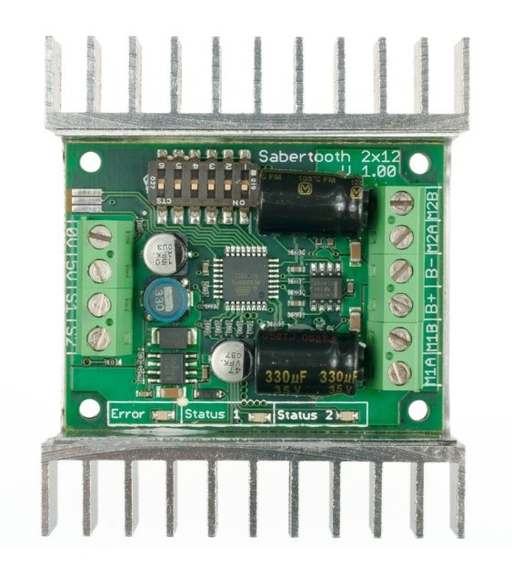
- Specifications
- Up to 18V in: 12A continuous, 15A peak per channel.
- 24V in: 12A continuous, 25A peak per channel.
- Synchronous regenerative drive
- Ultra-sonic switching frequency
- Thermal and overcurrent protection
- Lithium protection mode
- Input modes: Analog, R/C, simplified serial, packetized serial
- Size: 2.3” x 3” x .7”
- 59 x 75 x 17 mm
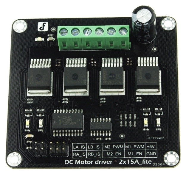
- Specifications
- Input Voltage:4.8-35V
- Maximum output current:15A@13.8V per channel
- Peak output current:20A@13.8V per channel
- PWM capability:up to 25 kHz
- Interfaces:4 digital IO(2 PWM output include)
- Driving mode:Dual high-power H-bridge driver
- Other specifications
- Galvanic isolation to protect the microcontroller
- Dual current detection diagnostic functions
- Short circuit, overheating, over-voltage protection
- Size:73x68x14mm
12V high quality and quiet DC Motor 146rpm w/Encoder
- Specifications
- Model:28PA51G
- Working voltage:12V
- No load RPM (before gearbox):8000 rpm
- Gear ratio: 51:1
- No load RPM (after gearbox): 146rpm@12V
- No load current: @ 12V: 0.23A
- Stall current:3.6A
- Rated torque @ 12V: 10kg.cm (139oz.in)
- Encoder Resolution: 13 PPR (663 PPR for gearbox shaft)
- Two phase hall encoder
- Size:123x36x36mm
- Weight: 270g
Can be connect on the Master then giving a method to control the HCR by wireless.
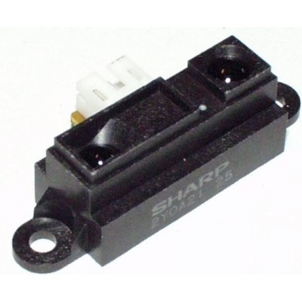
- Specifications
- operating voltage: 4.5 V to 5.5 V
- average current consumption: 30 mA (typical)
- distance measuring range: 10 cm to 80 cm (4" to 32")
- output type: analog voltage
- output voltage differential over distance range: 1.9 V (typical)
- response time: 38 ± 10 ms
- package size: 29.5×13.0×13.5 mm (1.16×0.5×0.53")
- weight: 3.5 g (0.12 oz)
Use digital pins.
- Specifications
- operating voltage: 4.5 V to 5.5 V
- output type: digital voltage
- size: 105×25×20 mm