-
Notifications
You must be signed in to change notification settings - Fork 5
Editing_Quad_Motor_Driver_Shield_for_Arduino_SKU__DRI0039

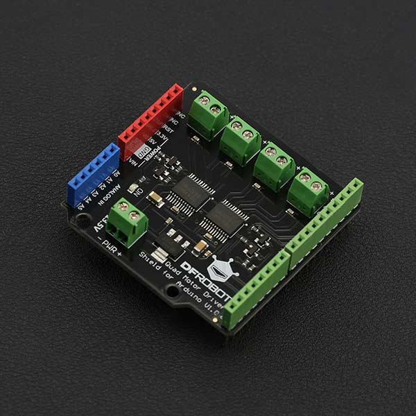
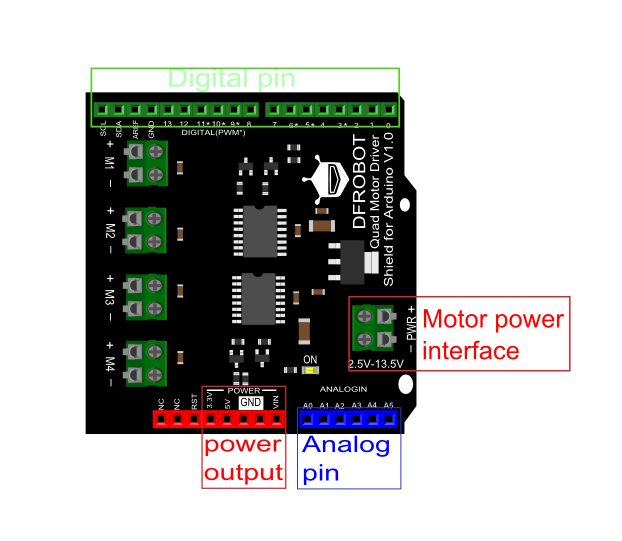
The latest quad motor driver shield for Arduino, compatible with 5V/3.3V Arduino controller, can control up to four DC motors with 8 pins at the same time. The shield supports PWM speed control and polarity control. The driver shield includes two TB6612FNG motor driver chips, compared with the traditional L298N chip, efficiency is improved and the component size also greatly reduced. The chip doesn't heat in to the rated range, and a single path maximum output 1.2A continuous current. The module includes a built-in low voltage detection circuit and thermal shutdown protection circuit, which is safe and reliable. This module is suitable for all kinds of DIY production.
- VM Motor Power Supply: 2.5 V ~ 13.5 V
- VCC Logic Power Supply: 2.7 ~ 5.5 V
- Output Current: 1.2A continuous current (per channel)
- Start/Peak Current: 2A (continuous pulse) / 3.2A (single pulse)
- Arduino Control Port: Digital pins 3, 4, 5, 6, 7, 8, 11, 12
- Working Temperature: -20 ~ 85 ℃
- Dimensions: 53mm x 52mm/2.09 x 2.05
 |
                                                   |-----------|---------------|-------------|--------------|-----------|-----------------|
                                                   | **Motor** | **Direction** | **Forward** | **Backward** | **Speed** | **Speed range** |
                                                   | M1        | 4             | LOW         | HIGH         | 3         | 0-255           |
                                                   | M2        | 12            | HIGH        | LOW          | 11        | 0-255           |
                                                   | M3        | 8             | LOW         | HIGH         | 5         | 0-255           |
                                                   | M4        | 7             | HIGH        | LOW          | 6         | 0-255           |  |
-
Hardware
- DFRduino UNO R3 x 1
- Quad Motor Shield for Arduino x 1
- DC motor x 4
- Jumper Wires
-
Software
- Arduino IDE Click to download Arduino IDE

/*!
* @file QuadMotorDriverShield.ino
* @brief QuadMotorDriverShield.ino  Motor control program
*
* Every 2 seconds to control motor positive inversion
*
* @author linfeng(490289303@qq.com)
* @version  V1.0
* @date  2016-4-5
*/
const int E1 = 3; ///<Motor1 Speed
const int E2 = 11;///<Motor2 Speed
const int E3 = 5; ///<Motor3 Speed
const int E4 = 6; ///<Motor4 Speed

const int M1 = 4; ///<Motor1 Direction
const int M2 = 12;///<Motor2 Direction
const int M3 = 8; ///<Motor3 Direction
const int M4 = 7; ///<Motor4 Direction


void M1_advance(char Speed) ///<Motor1 Advance
{
 digitalWrite(M1,LOW);
 analogWrite(E1,Speed);
}
void M2_advance(char Speed) ///<Motor2 Advance
{
 digitalWrite(M2,HIGH);
 analogWrite(E2,Speed);
}
void M3_advance(char Speed) ///<Motor3 Advance
{
 digitalWrite(M3,LOW);
 analogWrite(E3,Speed);
}
void M4_advance(char Speed) ///<Motor4 Advance
{
 digitalWrite(M4,HIGH);
 analogWrite(E4,Speed);
}

void M1_back(char Speed) ///<Motor1 Back off
{
 digitalWrite(M1,HIGH);
 analogWrite(E1,Speed);
}
void M2_back(char Speed) ///<Motor2 Back off
{
 digitalWrite(M2,LOW);
 analogWrite(E2,Speed);
}
void M3_back(char Speed) ///<Motor3 Back off
{
 digitalWrite(M3,HIGH);
 analogWrite(E3,Speed);
}
void M4_back(char Speed) ///<Motor4 Back off
{
 digitalWrite(M4,LOW);
 analogWrite(E4,Speed);
}


void setup() {
  for(int i=3;i<9;i++)
    pinMode(i,OUTPUT);
  for(int i=11;i<13;i++)
    pinMode(i,OUTPUT);
}

void loop() {
M1_advance(100);
M2_advance(100);
M3_advance(100);
M4_advance(100);
delay(2000); ///<Delay 2S
M1_back(100);
M2_back(100);
M3_back(100);
M4_back(100);
delay(2000); ///<Delay 2S
}
You should see the motor go forwards and backwards every two seconds
| For more questions or interesting projects, you can Visit the forum! |
Schematic Layout TB6612 Datasheet SVG files
 shopping from [link dfrobot store] or dfrobot distributor.