general_alignment
Sadly, there are only few good ressources on how to align optical systems, a few are:
- Philip Hobbs: Building Electro-Optical Systems: Making It all Work, 2nd Edition, Wiley 2009
- The chapter on optical alignment (written by Rainer Heintzmann) in: Ulrich Kubitschek: Fluorescence Microscopy: From Principles to Biological Applications, Wiley, 2017
- Usually, the mesoSPIM is a laser class 3B setup. Take all necessary precautions that come with this classification.
- Before each alignment step: Mentally prepare yourself for stray radiation and weird reflections. Where will they go? How to avoid them?
- Do alignment steps with low power laser beams first. Increase the intensity only when you are sure that you are close to good alignment.
- Do not do alignment steps in a rush or when tired. Take your time. Getting a setup up and running tonight is lovely, but never worth a fovea.
 To protect against stray laser beams, use magnetic beam blocks.
The mesoSPIM uses multi-laser combiners which are coupled into a single-mode fiber. By attaching a collimator to the fiber output, it is possible to create a laser beam source for alignment which can be placed at any location inside the optical system.
An example of such a collimator is shown here:

This collimator is build from the following parts:
- FLS40 20 mm carrier
- Microbench plate with SM1 thread (Custom)
- S120-FC FC/PC Fiber Adapter Cap with Internal SM1 (1.035"-40) Thread (Thorlabs)
- SM1M10 lens tube with internal threads (Thorlabs)
- SM1L05 lens tube (Thorlabs)
- SM1T10 lens tube coupler with external thread (Thorlabs)
- AC254-100-ML 100mm visible achromat (Thorlabs)
When building fiber collimators, please be aware of the difference between FC/PC and FC/APC connectors -- if an angled (APC) fiber is inserted into a straight (FC/PC) connector, the beam will exit at an angle. In this case, use a FC/APC fiber connector such as the Thorlabs SM1FCA. The achromat should be oriented as shown above (arrow in the direction of the beam). The interference pattern on the shear plate will behave in unexpected ways if the lens is used back to front.
If you don't have a separate fibre alignment laser and don't want to risk using your system's fibres you can build a simple collimator using a ThorLabs compact laser diode as shown below.

This unit uses a ThorLabs CPS532 4.5 mW laser but the dimmer 0.9 mW unit would also work. The beam is expanded by 4x using a LC1054-A f=-25 mm and a AC254-100-A-ML f=100 mm. The collimator is built out of SM1 lens tubes (SM1L20, SM1V10, SM1T1, SM1T2) with a KAD11F in an SM1 lens tube to allow the laser to be aligned with the beam expander.
Be aware that not all laser diodes / modules can be used for this application. Most diodes have insufficient beam quality. In addition, laser diodes can mode-hop - a phenomenon caused by temperature changes in the resonator. With a shear plate, mode-hops are visible as sudden shifts in the fringe pattern in a stable mechanical setup.
To collimate a monochromatic laser beam without sending it across the room and measuring its diameter on the wall, a shearing interferometer is extremely helpful. Using it, the collimation state of a beam can be inferred form the rotation of a fringe pattern or offset of two fringe patterns against each other. They are produced by various manufacturers, including Thorlabs and are very compact, thus allowing collimation checks in part of the setup that would be hard to reach otherwise.
Please familiarize yourself with the function of shearing interferometers here. There is also a Youtube video describing shear plates and how to use them for beam collimation:

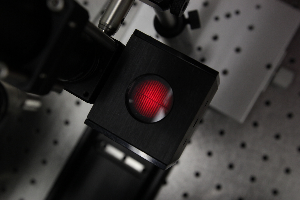
Example of a shearing interferometer cube (Mirage-Mirage) attached to a cage system. The beam is currently not collimated (different spatial frequency on both sides of the dark line between the fringe patterns).

Example of a collimated beam (similar spatial frequencies on both sides):
For some alignment tasks, autocollimation telescopes (autocollimators) are the ideal tool. You can find a guide to using autocollimators here
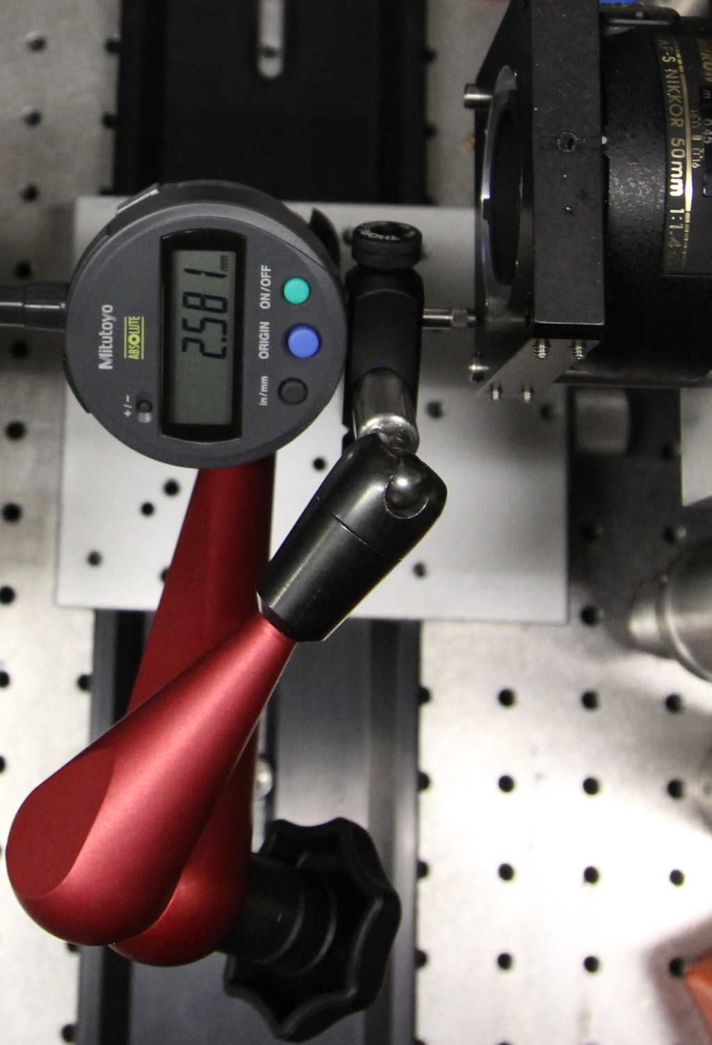
Typical mechanical adjustment tasks involve checking that two edges are parallel (e.g. a rail relative to another rail or a breadboard) can be made much simpler by using a position indicator. Here, we use a digital indicator manufactured by Mitotoyo and sold by Thorlabs. The indicator is placed on a movable arm (by Fisso) and can be used to indicate against any flat surface.
Using a position indicator to check whether a FLS95 rail is parallel to the motion axis of a linear stage. The slider of the stage is moved back and forth and the runout on the indicator checked.

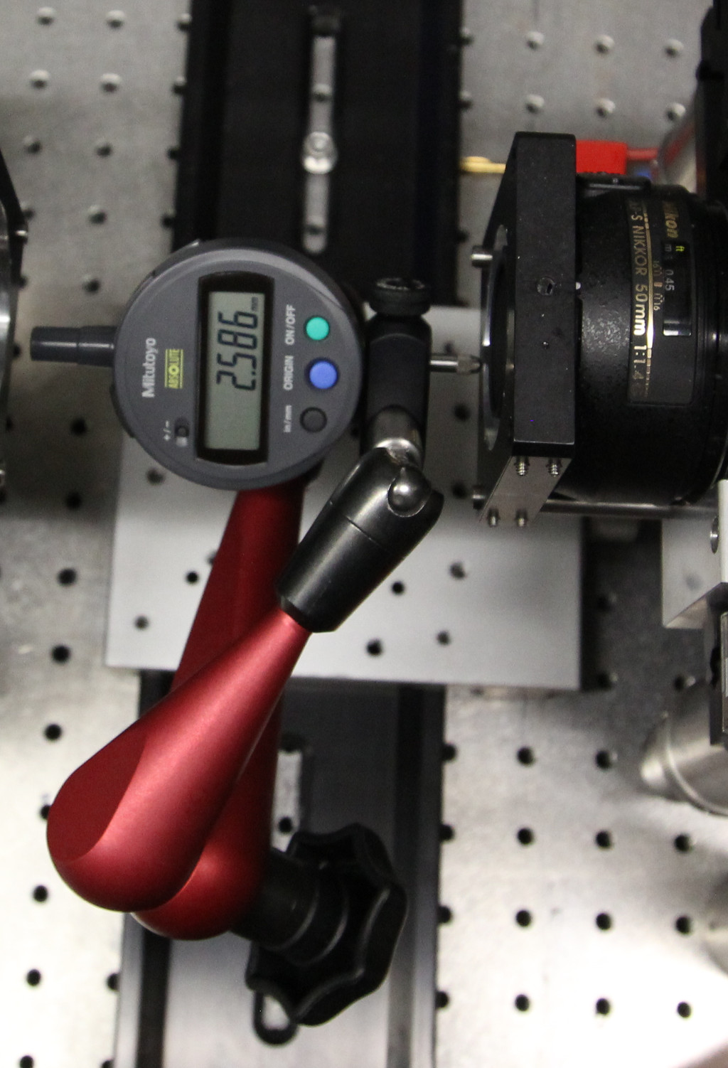
Another view of the same experiment, this time, the indicator has been moved to the other side of the FLS95 rail:

The digital indicator is used at various places throughout the setup and alignment procedure of a mesoSPIM, for example to check whether the excitation objective mounts are orthogonal to the central rail of the setup:
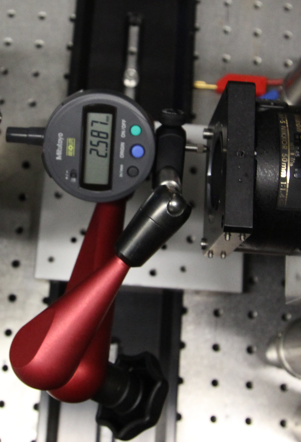
In this case, the runout is <10 µm -- which is enough (by far).
It's helpful to place a piece of packing foam on the air table on which to rest delicate parts for short periods
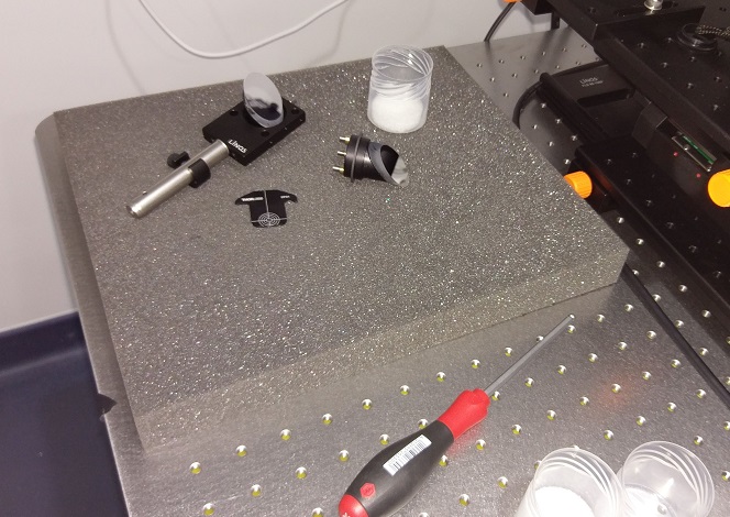
 As you progress through the steps for setting up the system, the optical table
will turn into a mess. Some tips to keep you organized:
As you progress through the steps for setting up the system, the optical table
will turn into a mess. Some tips to keep you organized:
- keep little boxes for small parts ready
- keep all your tools in one place
- keep cleaning supplies (duster, solvents, optical paper, microfiber cloths) ready
- document your steps with photographs