mesoSPIM_preparing_ETL_drivers
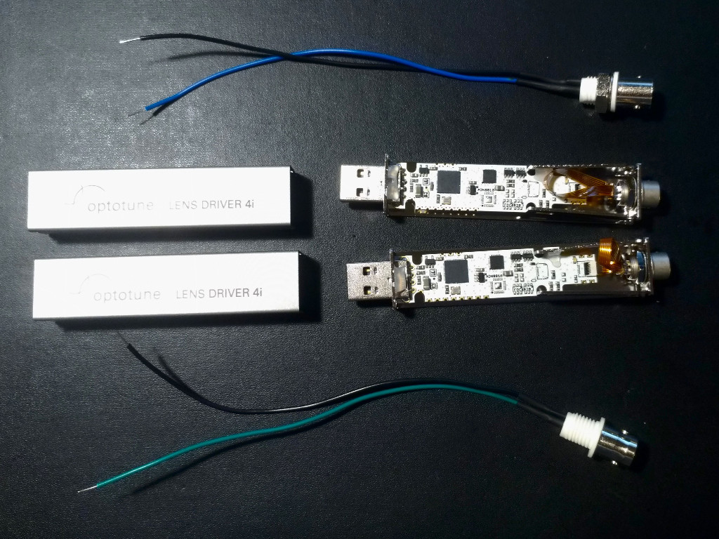
The mesoSPIM uses two electrically tunable lenses by Optotune to control the waist position of the excitation light-sheet (one in each excitation arm). The drivers (Optotune Lens Driver 4i) need to be modified with an BNC to analog input cable to allow control of the lenses via the National Instruments DAQmx analog outputs.
Documentation and Software for the lens drivers are available.
- 2x Lens Driver 4i
- 2x BNC Female connectors with wire leads soldered to the GND and signal pins
- Screwdriver
- Soldering equipment
- An adjustable 0-5 V source, this can be NI-DAQmx controlled or a function generation
- 1x BNC cable
- Open the Lens Driver housing at the Hirose connectors and remove the cover (see part 2.5. of the Optotune documentation)
- Push the wires through the opening at the bottom near the Hirose connector
- Solder the signal wire to the Analog In B pin (labeling is on the bottom of the PCB)
- Solder the GND wire to the GND pin (unlabeled pin next to the "Analog In A" and "Analog In B" pins )
- Close the housing

- Connect the lens driver to a PC via a USB port
- Run the "Lens Driver Controller Software"
- Connect to the lens
- Attach the function generator to the BNC input you soldered using a BNC cable
- In Extras/Sensor Control Configuration, enter the following values by setting the lens to the corresponding current and applying the corresponding voltage to the analog input, save using "Record Entry"
| Analog IN | Current |
|---|---|
| 0 (OV) | -292 mA (minimum) |
| 512 (2.5V) | 0 mA |
| 1023 (5V) | 292 mA |
- Switch operation to "Analog" mode and test e.g. with a sinusoidal signal whether the lens can be controlled from the function generator
- Unplug the driver from the USB port without closing the connection in the Optotune software. This way, the driver will stay in analog control mode.
- Connect the driver to a powered USB hub (no connection to a PC) and test whether the lens can be controlled with an analog input
- Repeat all steps with the second driver