mesoSPIM_excitation_path_M4_alignment
 In the next series of steps, the M4 mirror is inserted and aligned.
This is done using an alignment collimator with fold mirror attached
to the raised FLS-40 rail.
In the next series of steps, the M4 mirror is inserted and aligned.
This is done using an alignment collimator with fold mirror attached
to the raised FLS-40 rail.
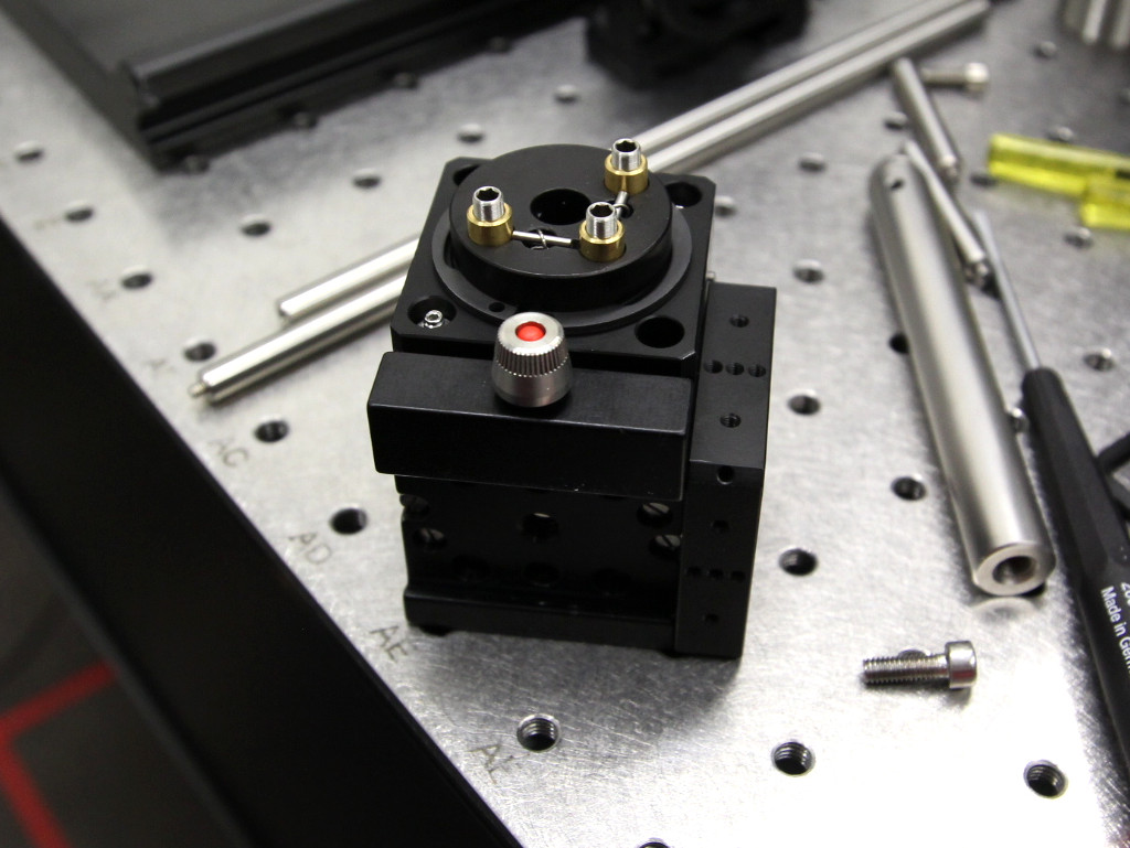
 By pressing the cage onto the flat optical table and against a spare 30 mm cage plate / microbench plate, the 40 mm FLS-40 carrier can be mounted without an offset.
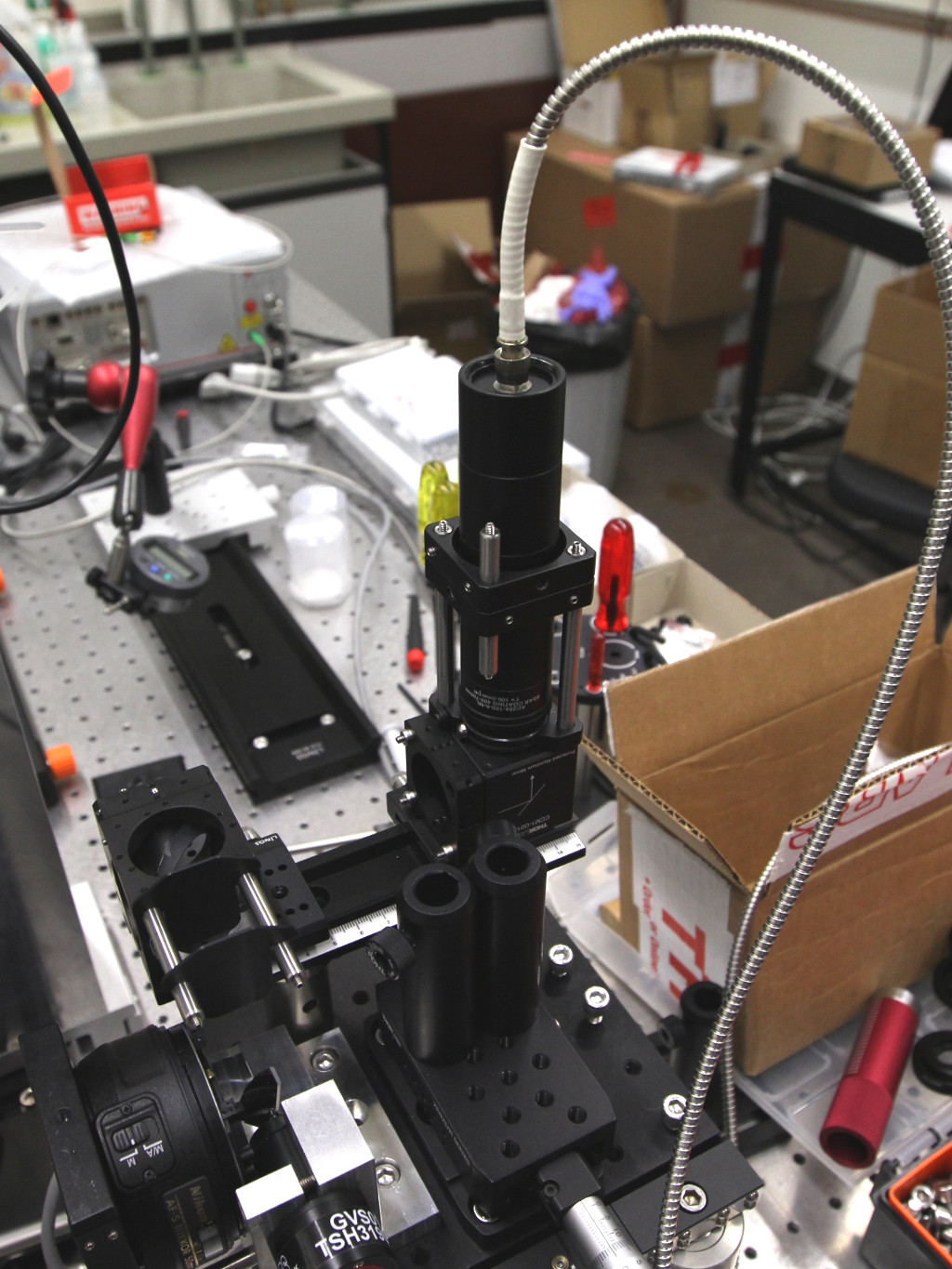
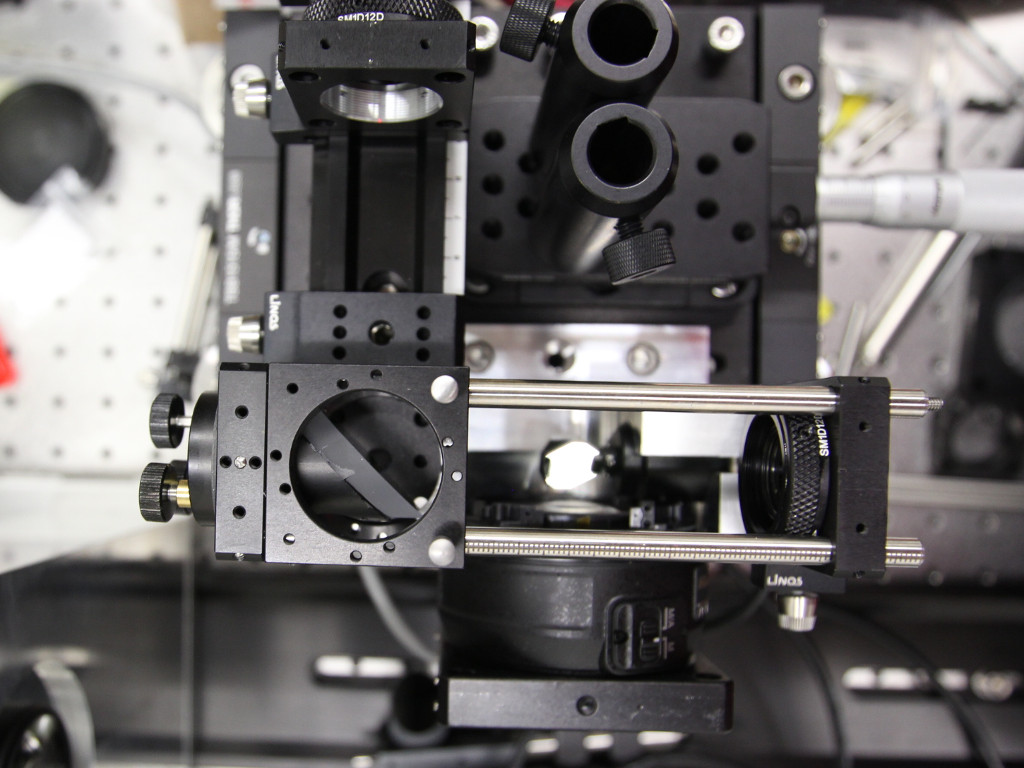
Add the 150 mm rail supported on each end by an RS2P/M post and PS5/M spacer. Add to the rail two irises mounted in 30 mm cage plates and the alignment beam, as shown below. Note that mounting the irises to the cage plates requires you to have modified cage plates threaded for ThorLabs SM1 components. Tighten the carriages and ensure beam is travelling straight down the rail. Do this by closing down the first iris to about 10 mm and then checking this is centred on the second iris. It ought to be very close. You can tweak the beam path by nudging the SM1 tubes holding the collimator.

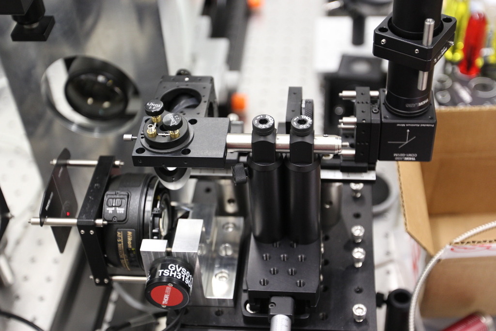
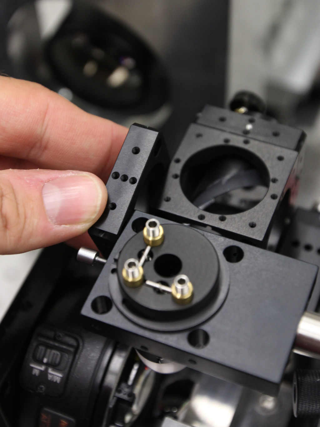
 Now you can replace the second iris with mounted mirror M4.
Add two ER4 rods and align the beam with them using M4.
Use the middle fine adjuster to translate the beam at the near position and the other two adjusters to tilt the beam at the far position.
Now you can replace the second iris with mounted mirror M4.
Add two ER4 rods and align the beam with them using M4.
Use the middle fine adjuster to translate the beam at the near position and the other two adjusters to tilt the beam at the far position.
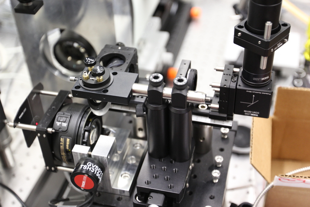
As the scanner mount is also 40 mm wide, a cage plate can be used as a reference to set up the 40 mm cube correctly on the raised FLS-40 rail:

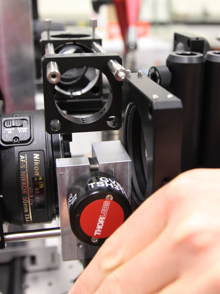
Using a spare plate, it is possible to make the cube and the holder 30 carrying M5 flush:
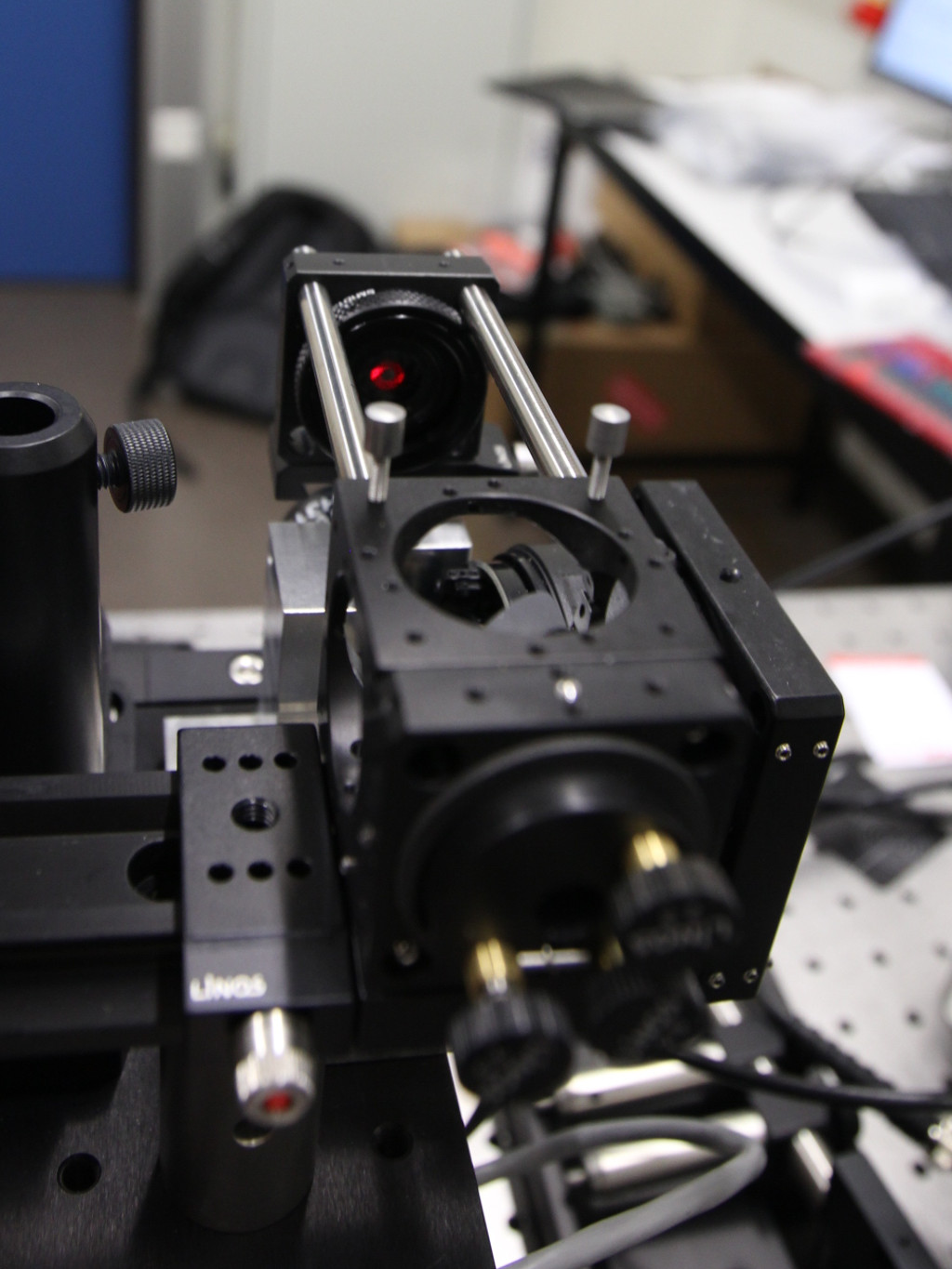
Overview of the alignment laser attached to the raised FLS-40 rail.