mdibl_camera
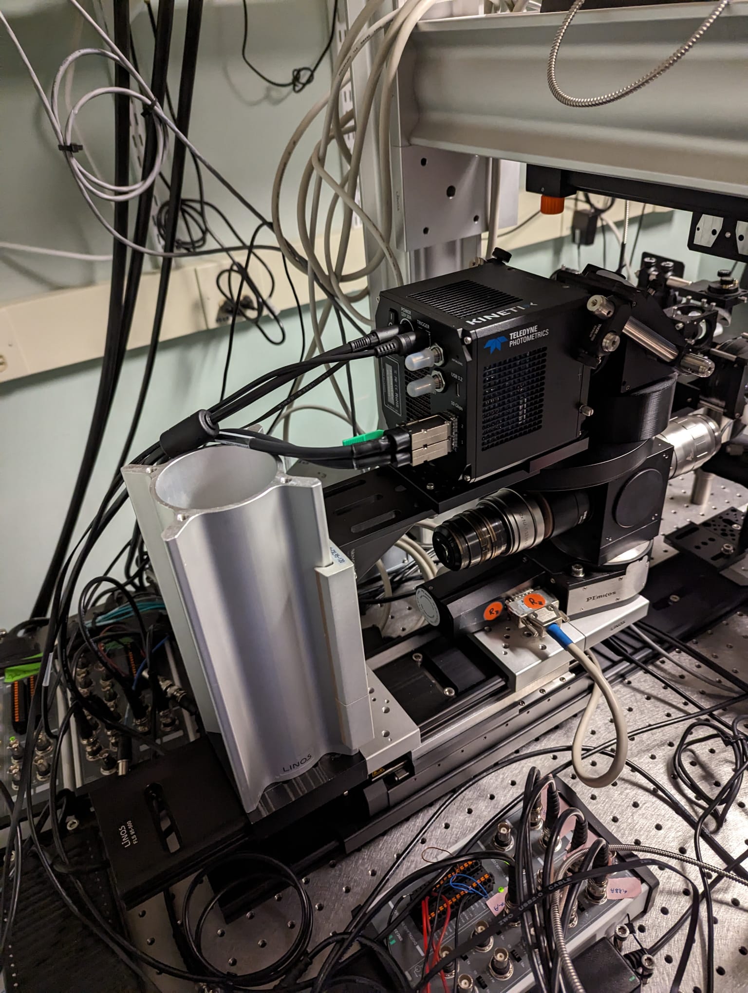
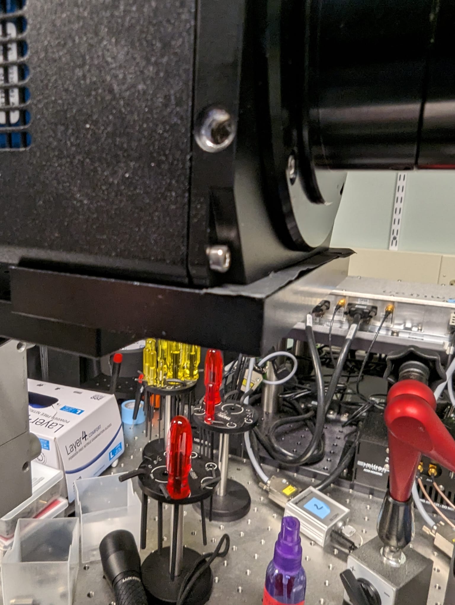
The camera path / module contains the Kinetix camera, a fold mirror, the tubelens, and the 2" filterwheel. The entire module is attached to a vertical 250 mm X95 profile using a carrier. This allows vertical translation of the entire module (to set the distance between filter wheel and the turret cube) and translation along the detection axis (to center the filterwheel above the turret cube).
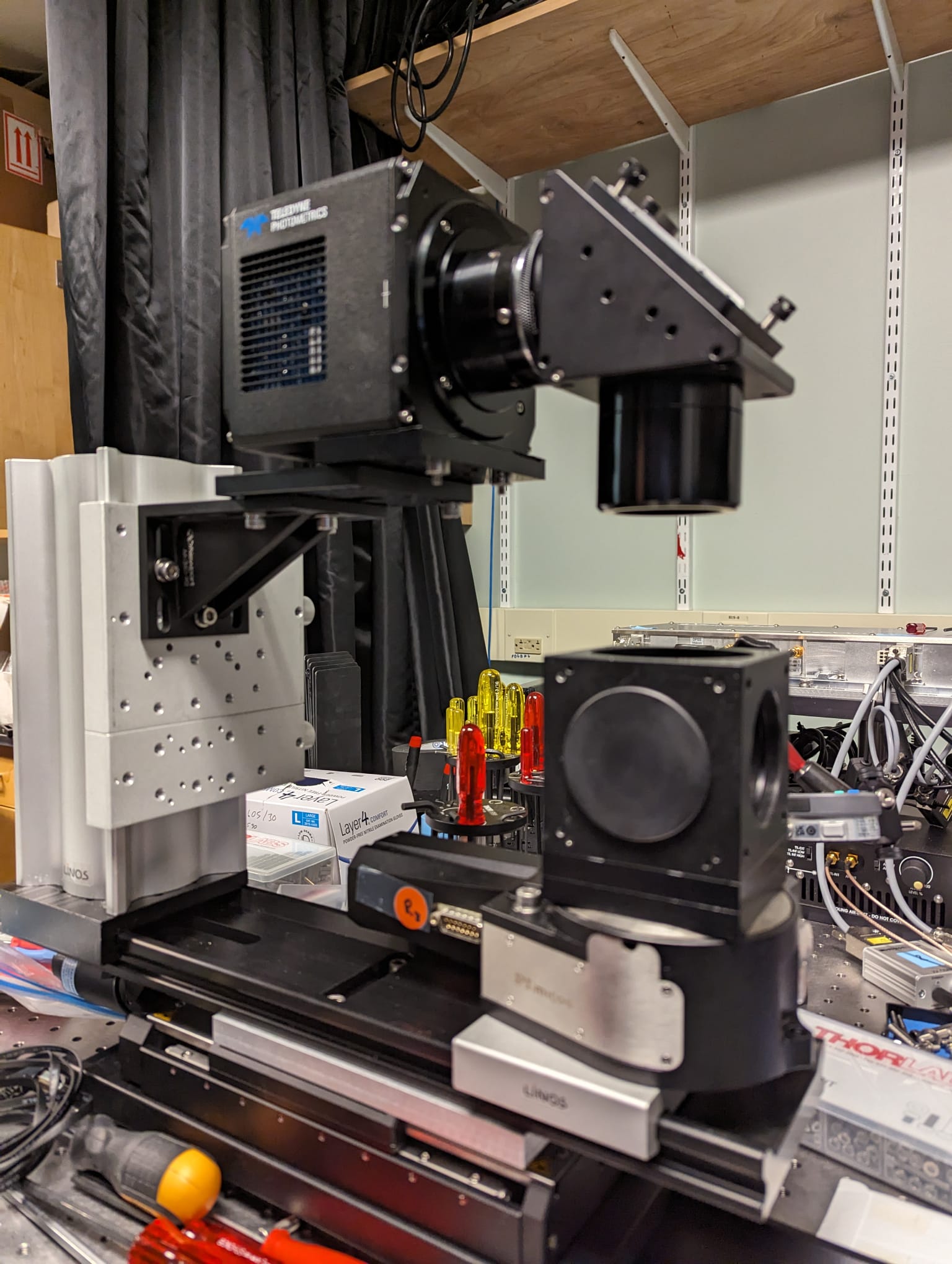
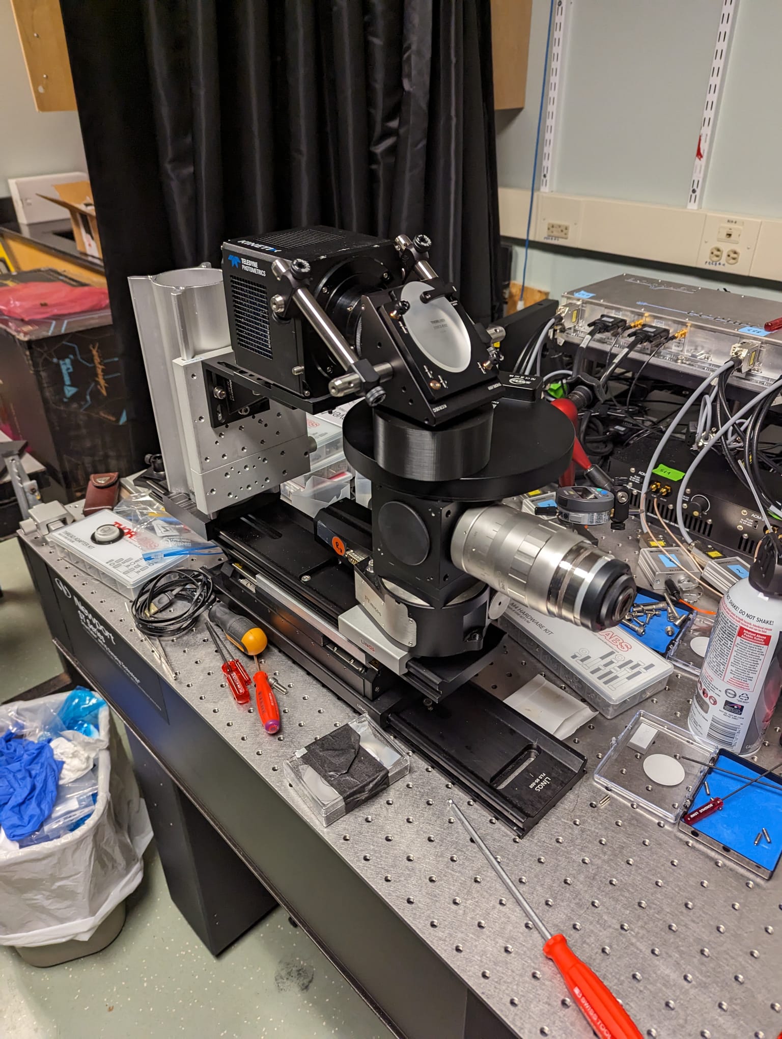 Raised camera for assembly.
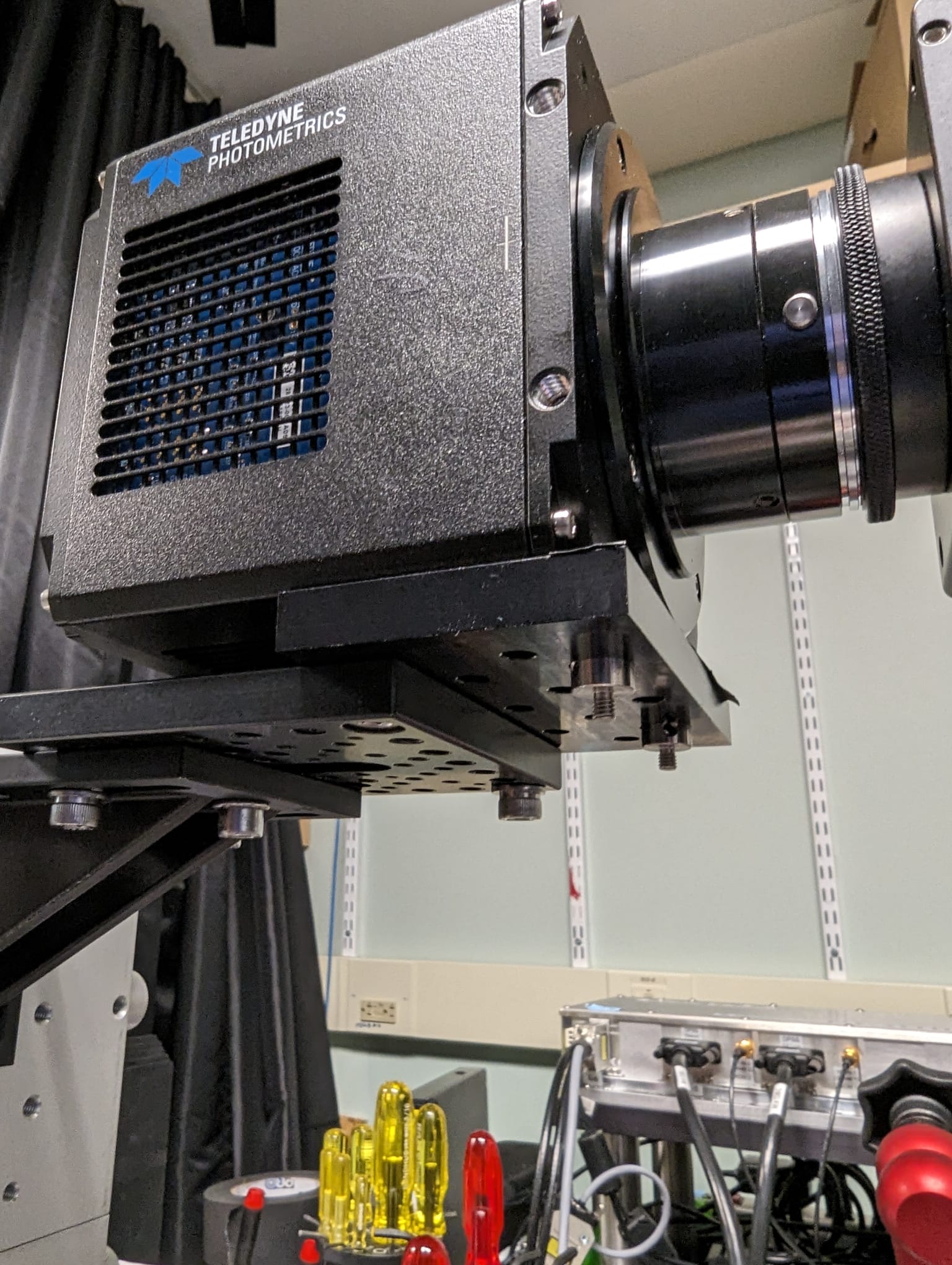
There is a special adapter plate that has holes with M6 thread on a 25/12.5 mm grid. It also allows connecting the camera using two 1/4 inch screws. The Kinetix mounting holes are 54 mm apart which means this adapter is required. Sadly, the camera threads are not flush with the rest of the housing -- therefore, shimming with two layers of black aluminium foil was necessary. The Thorlabs F-Mount adapter was screwed into the fold mirror mount using a 0.3 inch SM2 tube (SM2L03).
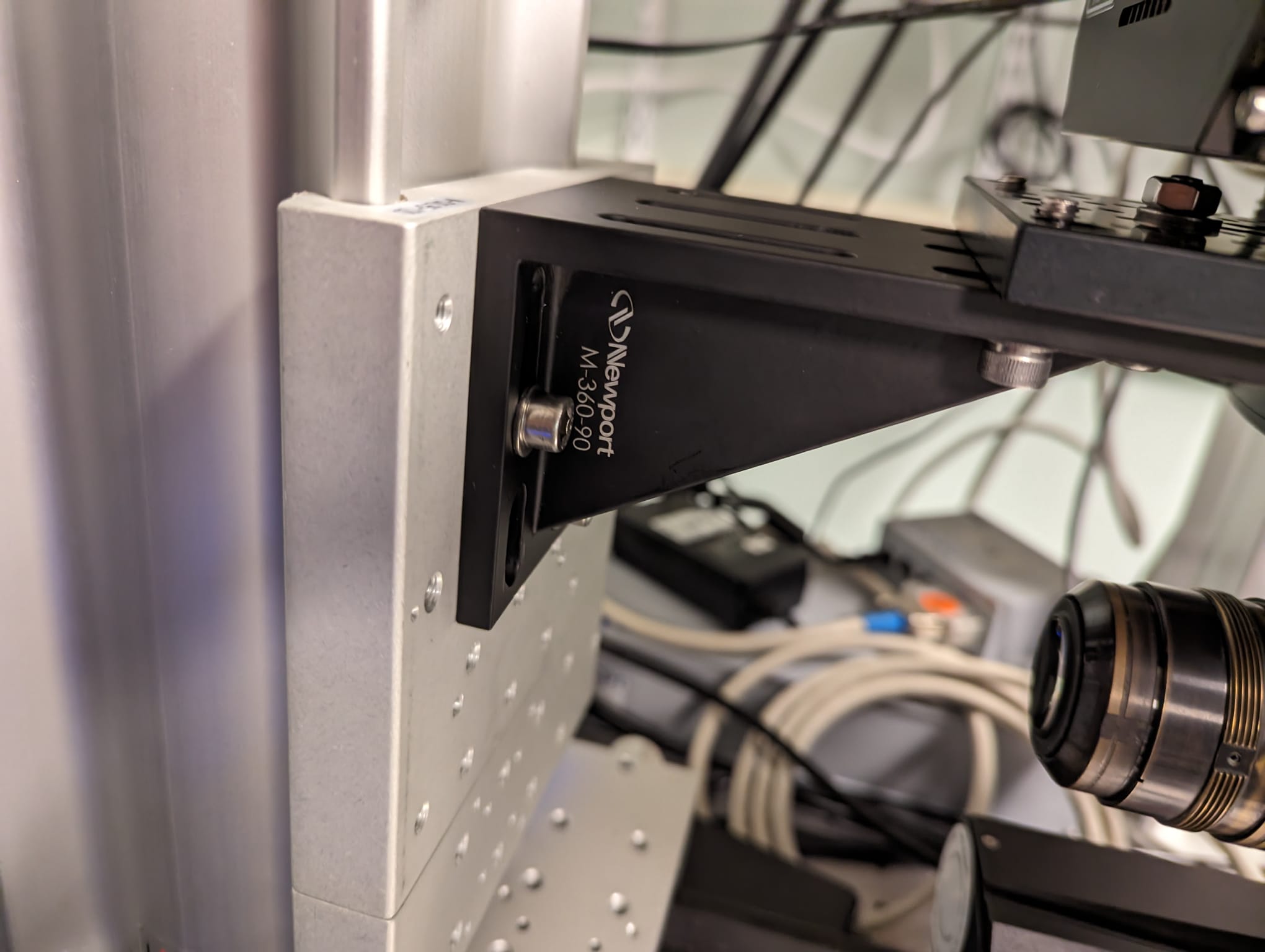
Use a water level to make the bracket as horizontal as possible.
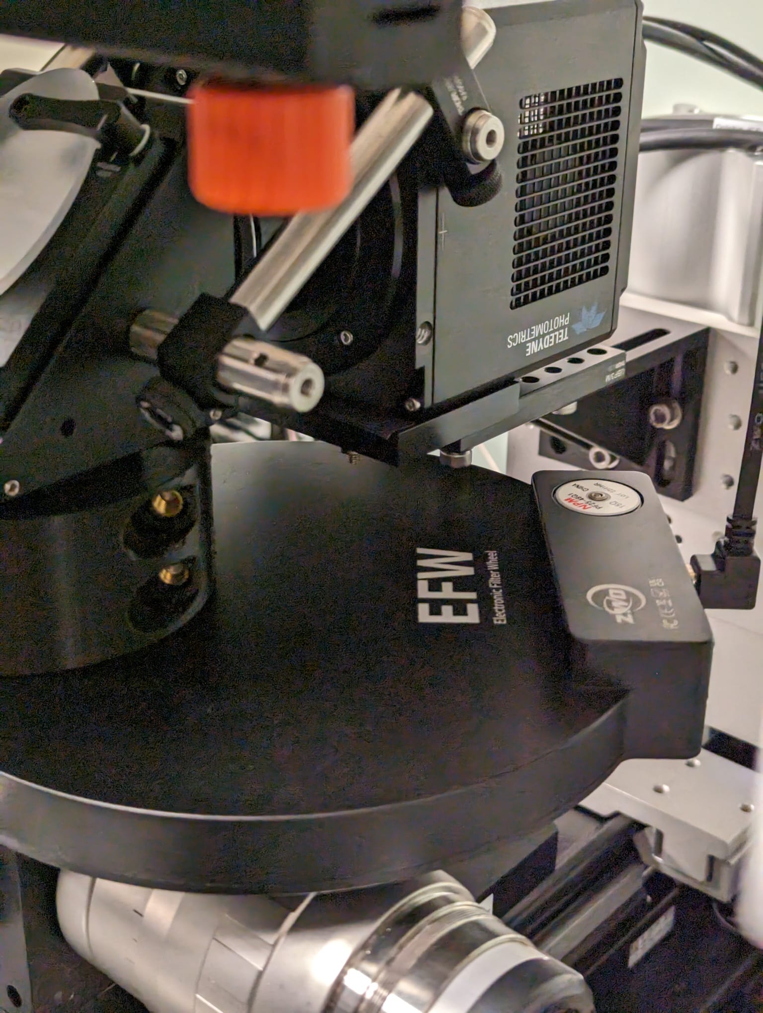
- you can use the screws holding the F-Mount adapter of the Kinetix to rotate / level the DM2 assembly relative to the camera
- use an autocollimator to check focus after assembly -- in the prototype, the focus was correct right away
As the Nikon F-Mount connector is not very stable, additional stabilizing rods connecting the camera and the fold mirror are useful (see first photo on this page).