mesoSPIM_excitation_path_ETL_assembly
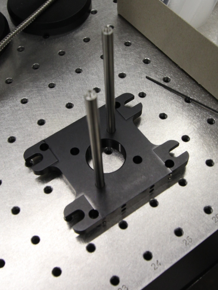
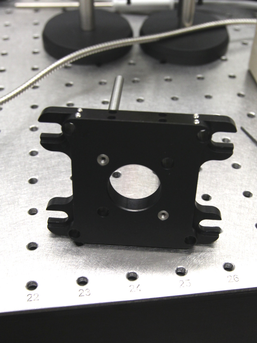
Both the ETL and the laser collimator path are based on Thorlabs CPVM vertical cage system mounting plates. To be able to have independent cage systems to the top and bottom of this plate, each side has two cage rods. First, put 2 4-inch 6-mm rods in the bottom 30 mm cage holes, fix them and ensure they are flush with the top surface.
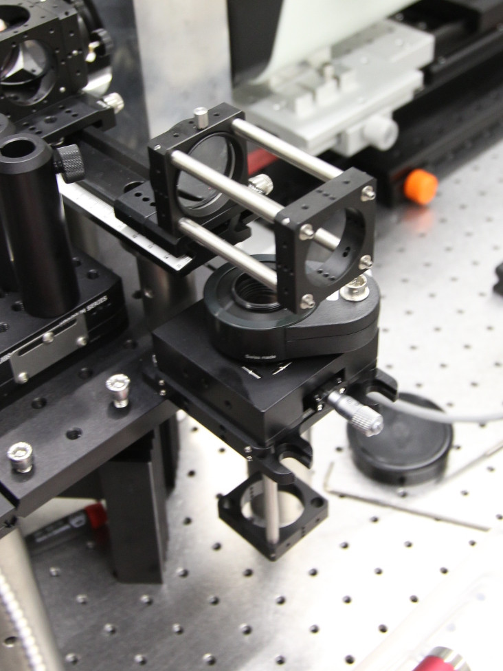
Then, center the XY mount for the ETL and insert two 1-inch cage rods in the bottom threads:
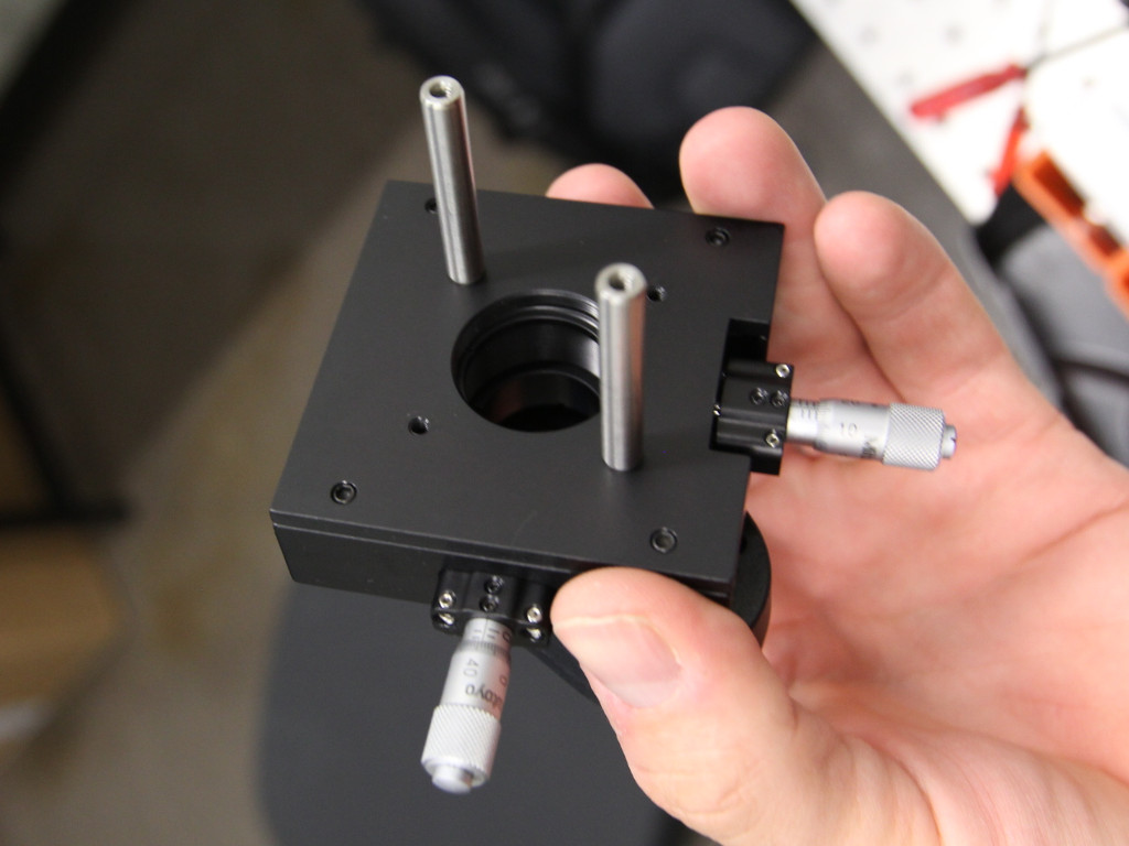
You can attach the ETL via a C-Mount to SM1-adapter. The two inpendent rod systems now allow independent movement of the axial ETL-position without affecting the position of the folding mirrors M1 and M2.

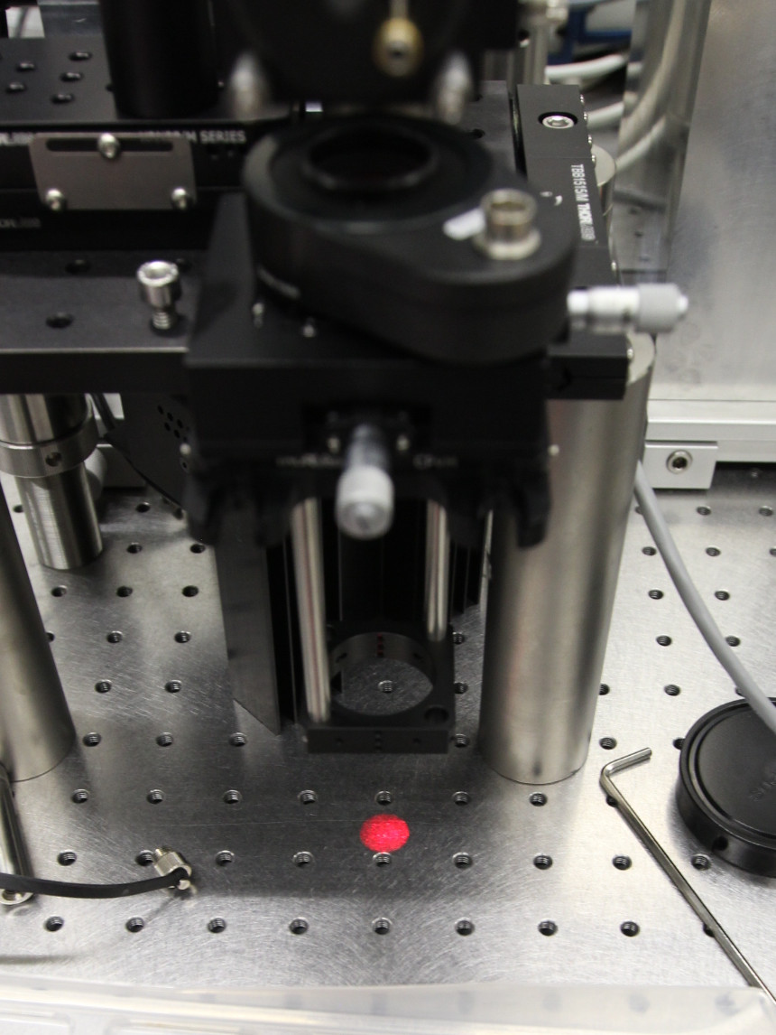
The ETL path can then be inserted. You can use an additional carrier on the FLS-40 rail to allow removal of L3 without changing its position.

Make sure that the fold mirror (M3) is on top of the ETL aperture and directs the beam downwards. One way of accomplishing this is to remove L3 from the 35 mm cage plate (which means L3 needs to be collimated again). You can also "mark" the position of L3 by clamping an additional FLS40 carrier to the rail.