mesoSPIM_optical_design_excitation_arm
The optical path of the mesoSPIM was designed with the following parameters in mind:
- excitation wavelengths from 400-650 nm, ideally up to 750 nm
- NIR wavelengths are a recent addition to allow using secondary antibodies conjugated to near-infrared fluorophores.
- a light-sheet that fills a 21 mm field-of-view (FOV)
- this allows to fill the whole FOV of the MVPLAPO 1x objective in combination with a MVX-10 zoom body and a Hamamatsu Orca Flash 4.0 V3 sCMOS camera
- tunable-lens based refocusing with a tuning range of at least 21 mm (corresponding to the maximum FOV of the detection arm at zoom 0.63x)
- reduction of shadowing by using a scanned light-sheet approach similar to early-generation Lavision Ultramicroscopes (Ultramicroscope I)
- to aid in shadow reduction, the excitation NA should be at least 0.1, better: 0.15
- coalignment of both light-sheets should be easy
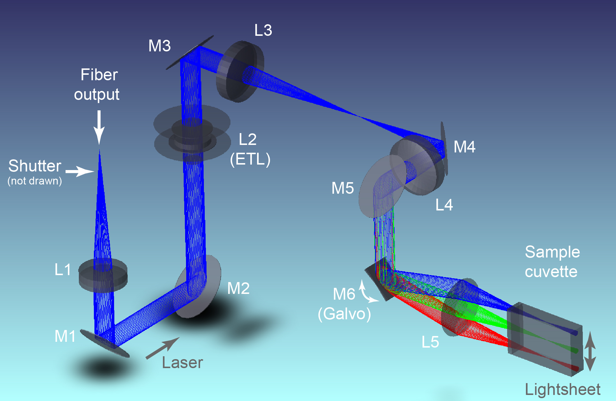
After passing through the shutter aperture, light from the fiber output is collimated by L1 and then redirected to the electrically tunable lens (ETL). A 1:1 relay than reimages the ETL onto a galvo mirror (M6). By scanning the Gaussian beam in a single axis, a light-sheet is created using a f=50 mm DSLR objective (L5). For simplicity, L5 is drawn as a single paraxial lens instead of showing the internal structure of the objective. The fold mirrors M1 to M5 render the system more compact. The colors indicate the ray path at different positions of the scan mirror.
| Component | Order Number | Description |
|---|---|---|
| L1 | Thorlabs AC254-075-A-ML | f=75 mm, Ø1" Achromatic Doublet, SM1-Threaded Mount, ARC: 400-700 nm |
| L2 | Optotune EL-16-40-TC-VIS-5D-1-C | Tunable lens with focal power range: -2/+3 diopters |
| L3 & L4 | Qioptiq G063200000 | Achromatic doublet VIS ARB2; D=31.5; F=80; mounted |
| L5 | Nikon AF-S 50 mm f/1.4 G | DSLR objective used as a scanlens. The galvo mirror M6 is mounted in its back focal plane. |
| M1-M5 | Thorlabs BB1-E02 | 1" Broadband Dielectric Elliptical Mirror, 400 - 750 nm |
| M6 | Galvo mirror: Either Thorlabs GVS211/M (10 mm) aperture or Scanlab dynAXIS 3M (14 mm) |
Early tests showed that typical CLARITY-cleared mouse brains can expand up to 20 mm in length. While most samples are much smaller than that, it is highly beneficial to have a large FOV for sample positioning.
Initially, we used the MVPLAPO2x for light-sheet imaging, however, the distortion at the edges was very noticable. We therefore compared the 1x and 2x objectives and found the 1x to be better. While this limits the zoom range to a minimum FOV of 2.1 mm, it has better overall image quality. In addition, we found that due to the significantly higher spherical aberration at higher magnifications, very little imaging is actually done between 6.4x - 12,6x using the 2x objective.
We compared the distortion properties using a test grid with 0.25 mm spacing (Thorlabs R2L2S3P2 Grid Distortion Target, 1.5" x 1.5", 250 µm Grid Spacing). The grid was immersed in 10 mm of immersion oil (Cargille Code 50350 nD=1.4587 fused silica matching oil) to simulate effects in the imaging cuvette. As the optical system is not telecentric over the whole zoom range, the refraction at the cuvette introduces additional distortion even if the objective is distortion-corrected.
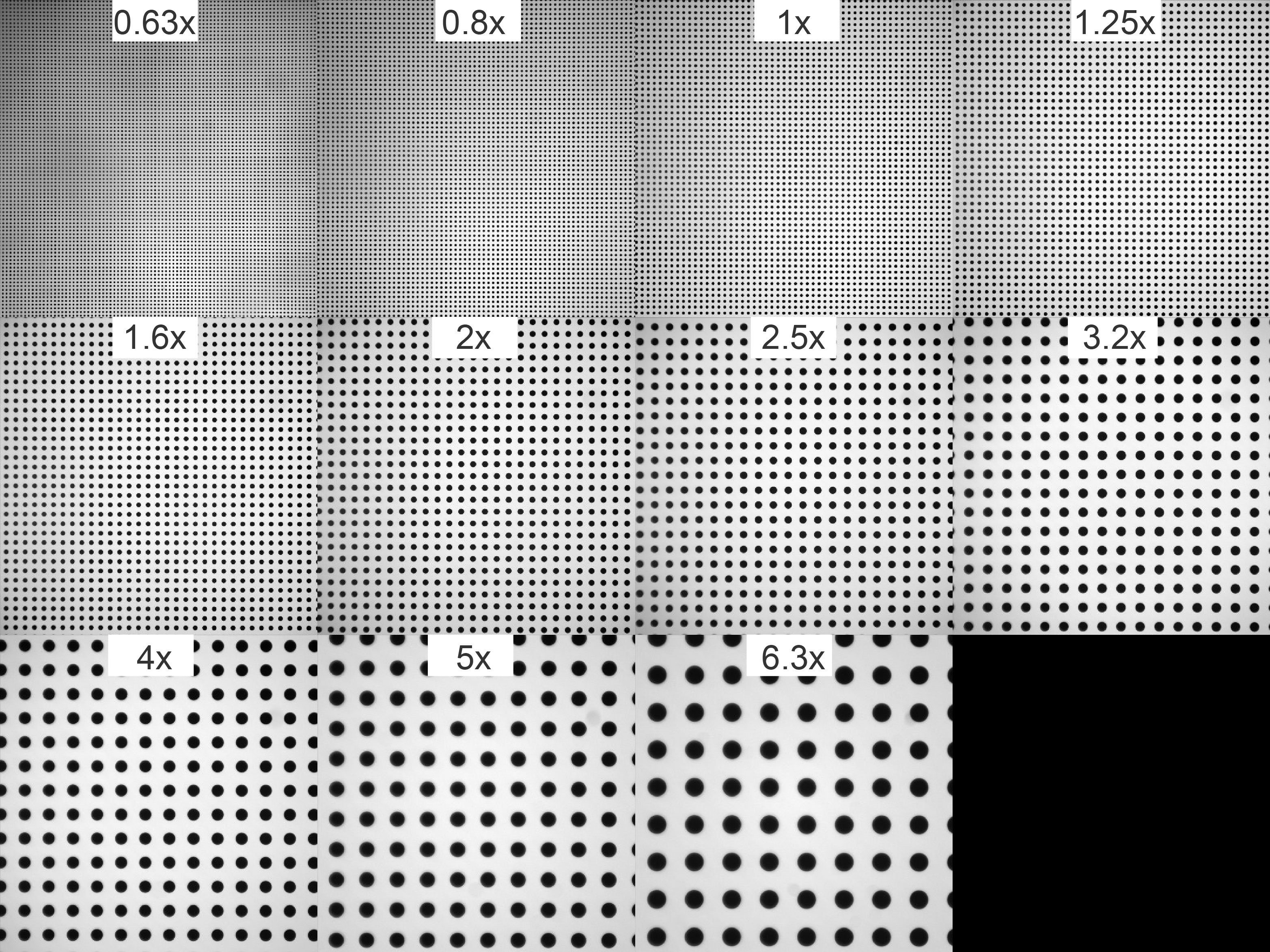 Above: Distortion measurements with the 1x Objective. At 2.5x, slight pincushion distortion
is visible.
Above: Distortion measurements with the 1x Objective. At 2.5x, slight pincushion distortion
is visible.
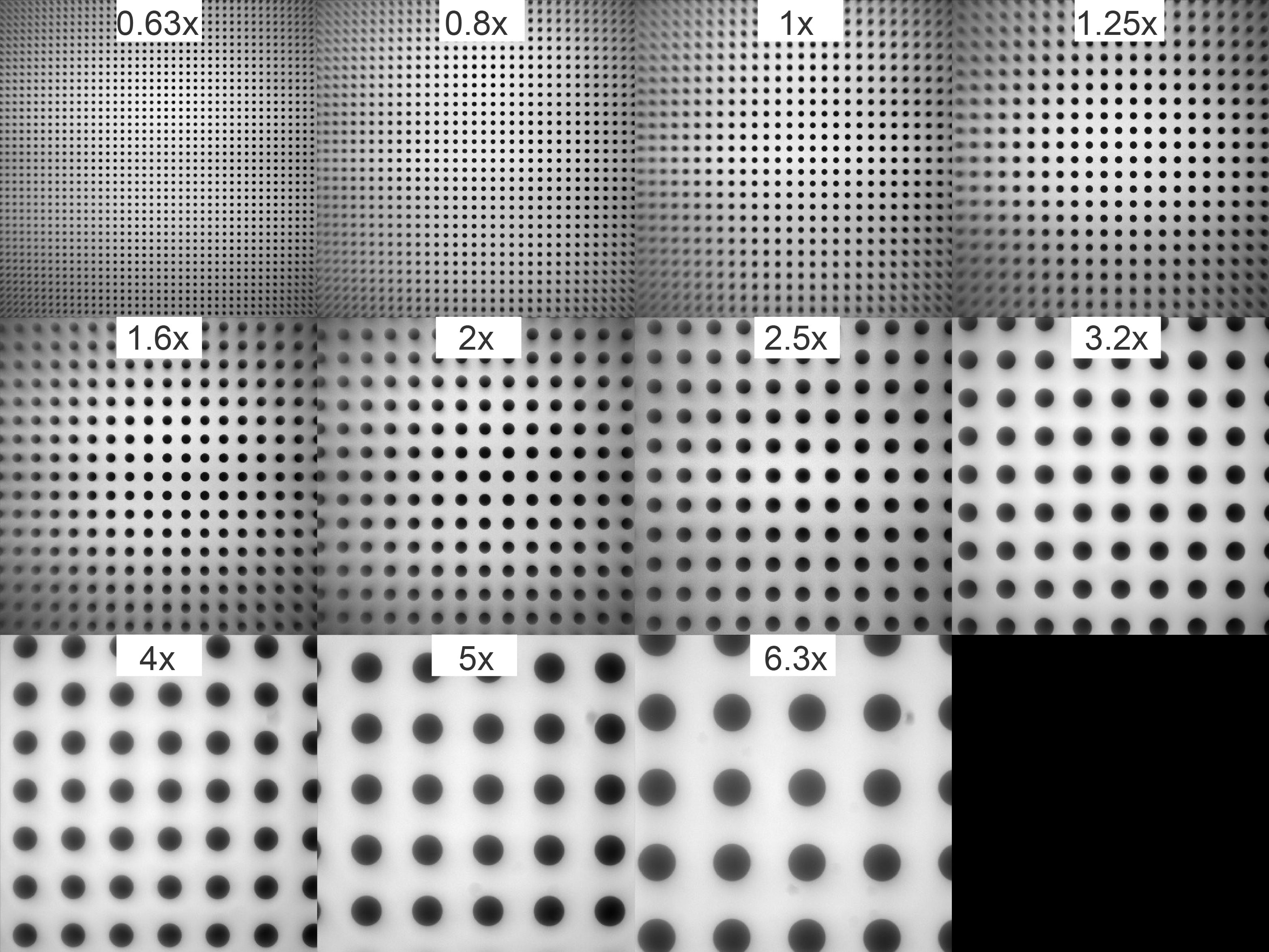 Above: Distortion measurements with the 2x Objective.
Especially between zoom 1x and 2x (corresponding to FOVs of 7 mm and 3.5 mm, respectively), massive distortion
and field curvature can be seen. This causes severe problems for tiled acquisitions.
Above: Distortion measurements with the 2x Objective.
Especially between zoom 1x and 2x (corresponding to FOVs of 7 mm and 3.5 mm, respectively), massive distortion
and field curvature can be seen. This causes severe problems for tiled acquisitions.
We therefore decided to use the MVPLAPO1x and designed the excitation path for the corresponding parameters. This has the additional advantage of allowing easy exchange of imaging cuvettes as there is air all around the sample chamber and due to the long working distance of the 1x objective (65 mm in air), exchanging sample cuvettes to switch between clearing media is straightforward.
To reduce the impact of distortion, the current generation of Lavision Ultramicroscopes is sold with special dipping caps for the MVPLAPO 2x containing lenses for field-flattening and distortion reduction (if a MVX-10 zoom body is used). A similar approach would be possible with a mesoSPIM - due to the horizontal geometry, however, the dipping cap would need to be part of the sample chamber.
The first SPIM used cylindrical lenses for the generation of the light-sheet. In such a system, changing the lateral size of the sheet (for example, to accomodate detection objectives with different field-of-views), requires either truncation of the beam using an aperture mask or elliptical beam-shaping. In a zoom system as used with the mesoSPIM, the light-sheet width has to be changed by a factor of 10x, which poses a challenge for optical design. In addition, reshaping a Gaussian beam into a light-sheet in this way usually leaves the Gaussian profile intact, which means that there is an intensity fall-off towards the edges of the FOV.
While more complicated beam-shaping techniques are possible (such as the conversion of a Gaussian beam profile to a Top-hat profile by aspheric lenses), this is challenging because the system has to perform well over a wide range of wavelengths.
In a digitally scanned light-sheet microscope (DSLM), the illumination profile is flat up to the edges. For imaging living samples, a SPIM design can have benefits compared to a DSLM in terms of photobleaching and phototoxicity as the peak power of the illumination is much lower. For imaging, fixed samples as in a mesoSPIM, this is less critical.
A classical artifact in light-sheet microscopy are shadows caused by partial absorption or refraction of the light-sheet as it penetrates through the sample. One way to reduce the impact of shadows during acquisition is to pivot the light-sheet in the excitation plane. In this way, the shadows are "filled in" by illumination from different angles. This method was first published by Huisken & Stanier in 2009) and is termed multidirectional SPIM or "mSPIM". Other approaches use post-processing of the datasets. Depending on the quality of the desired reduction in shadows, such methods range from Fourier filtering of the images to variational stationary noise removal. Especially when both very fine and coarse structures are supposed to be visualized, proper removal of stripe artifacts without introducing other artifacts can be computationally very intensive.
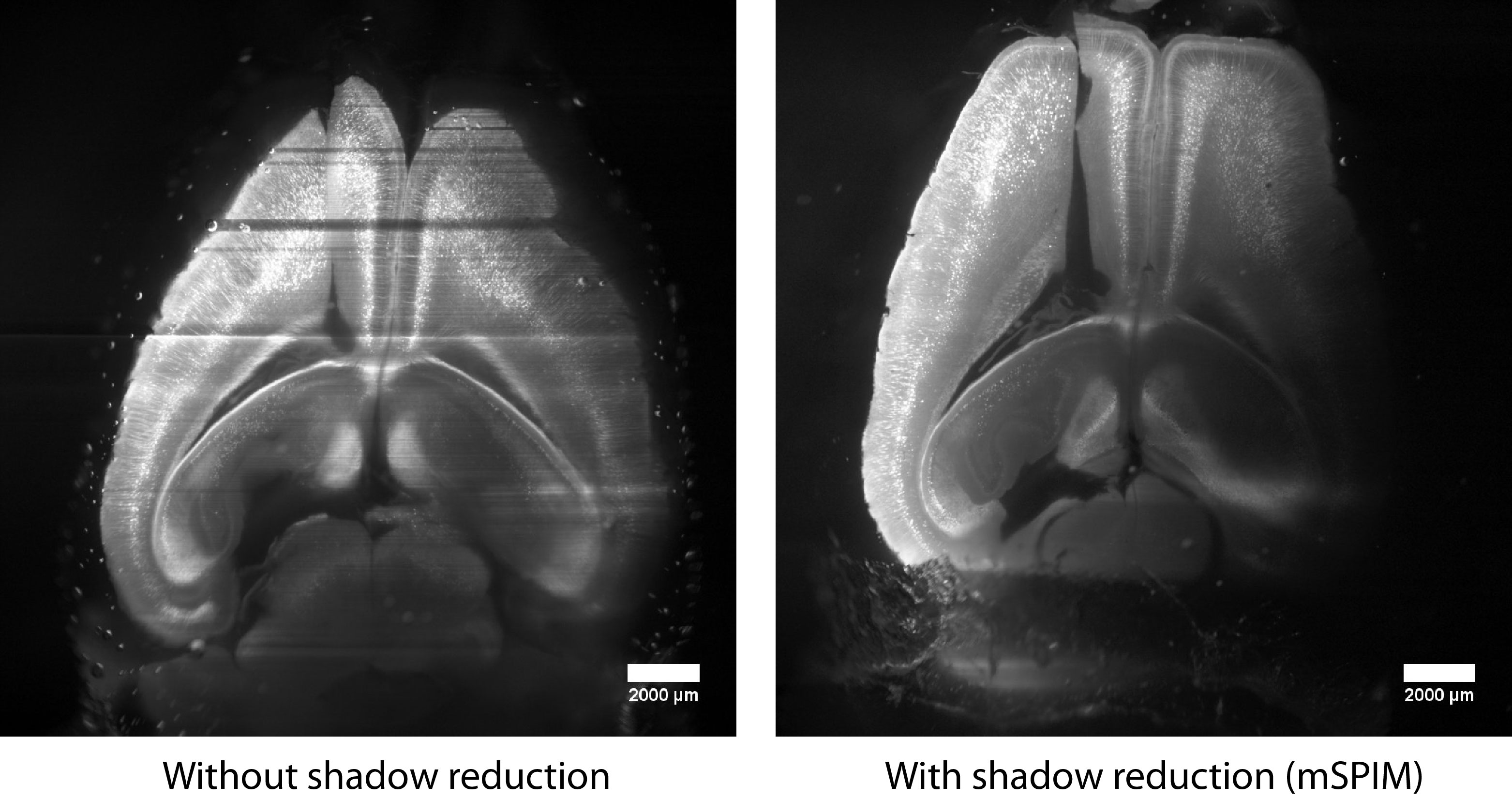 Comparison of images of a Thy-1 YFP mouse brain cleared with the CLARTIY
method in a standard light-sheet microscope using a cylindrical lens (left)
to a multidirectional SPIM (right). In the case on the left, shadows (for
example caused by bubbles) are visible throughout the plane. With mSPIM,
the illumination is very homogeneous. In both cases, the intensity
gradient (left-to-right) is caused by bulk absorption in the sample
(the light-sheet is entering from the left).
Comparison of images of a Thy-1 YFP mouse brain cleared with the CLARTIY
method in a standard light-sheet microscope using a cylindrical lens (left)
to a multidirectional SPIM (right). In the case on the left, shadows (for
example caused by bubbles) are visible throughout the plane. With mSPIM,
the illumination is very homogeneous. In both cases, the intensity
gradient (left-to-right) is caused by bulk absorption in the sample
(the light-sheet is entering from the left).
We therefore decided that a mesoSPIM should provide raw data of the best possible quality, so we opted for a excitation path with build-in shadow reduction. This way, users do not have to worry about shadowing (unless very large structures obstruct the light-sheet on its way.) and data does not need to undergo lengthy processing before it can be visually inspected.
Co-alignment of two counter-propagating light-sheets is a classical problem in light-sheet microscopy. In a DSLM, the tilt of the light-sheet can be changed by translating the beam over the aperture of the excitation objective. Especially for light-sheet microscopes with high NA in detection (such as a Bessel beam instrument), this is highly beneficial.
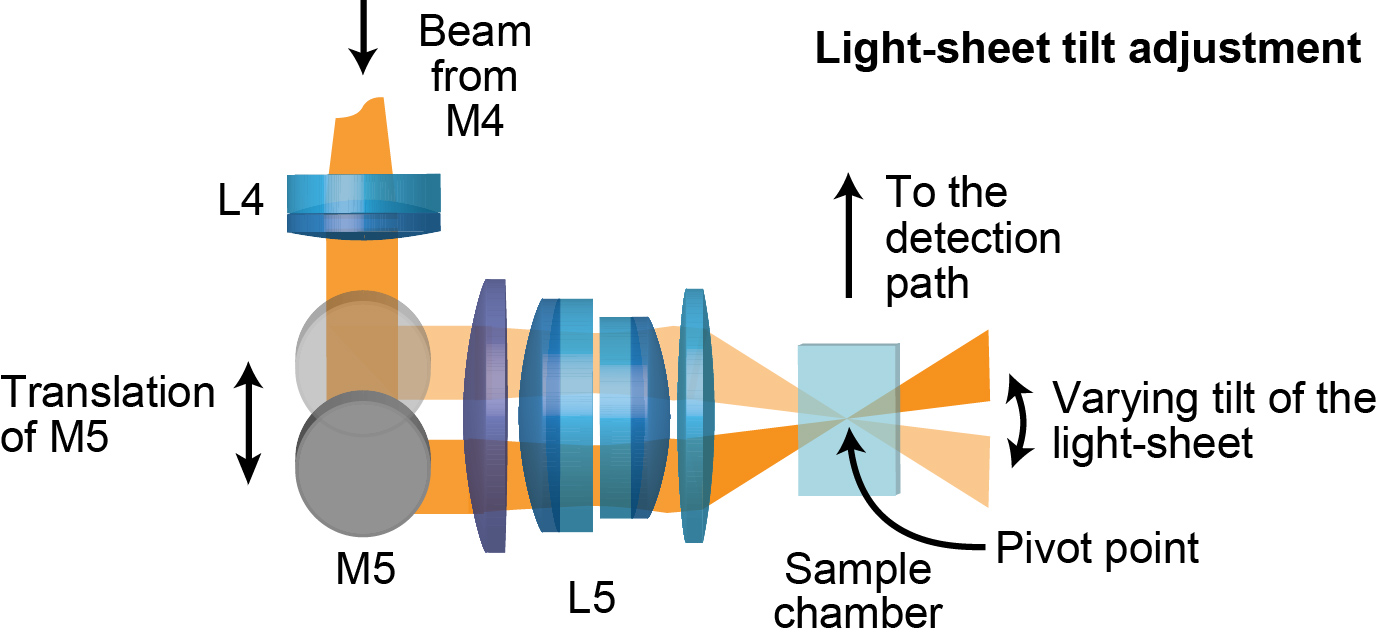 By putting the last mirror on a linear stage and translating it along the
direction of the input beam, we can adjust the tilt of the light-sheet.
In the ideal case, the tilt is clean (i.e. the pivot point of the light-sheet inside
the sample does not move depending on the pivot angle.) In reality, the pivot
point moves - one reason being that the high-index medium inside the sample
chamber induces refraction of the excitation light-sheet which shifts the pivot point.
By putting the last mirror on a linear stage and translating it along the
direction of the input beam, we can adjust the tilt of the light-sheet.
In the ideal case, the tilt is clean (i.e. the pivot point of the light-sheet inside
the sample does not move depending on the pivot angle.) In reality, the pivot
point moves - one reason being that the high-index medium inside the sample
chamber induces refraction of the excitation light-sheet which shifts the pivot point.
Initial tests with mesoSPIM prototypes showed that a scanned Gaussian beam with an
excitation NA of 0.14 - 0.15 yielded acceptable reduction of shadow artifacts over the FOV. The scan lens path has to be telecentric, otherwise the height of the light-sheet (in the Y direction) does not stay constant during remote focusing as required for ASLM. Any change in height will also be a nuisance as the light-sheet intensity will vary across the FOV: If the light-sheet height is not constant, the available laser power will be more concentrated in certain parts
of the FOV. In typical DSLM instruments, the excitation path
is similar to typical confocal excitation paths with a combination of scanners, a scan and tube lens and a microscope objective. As we needed more than 20-mm FOV due to our large detection FOV, we deemed standard microscope optics as inadequate as there are no low-magnification objectives with sufficient working distance (> 25 mm) and NA (>0.1). One of the closest approximations to the mesoSPIM requirements, the Olympus XLFLUOR 4x NA 0.28 with a working distance of 29.5 mm is designed for a field number of 22, corresponding only to a 5.5 mm FOV. However, the design of the scan path can be simplified by removing the tube lens and objective altogether: By combining a single-axis galvo scanner with a scan lens
of sufficient NA and working distance, creating a light-sheet of more than 20-mm height after the scan lens should be feasible.
 Challenges and solutions in the optical design of the mesoSPIM
excitation scan lens. a) List of scan lens requirements. b) The scan system has to be telecentric to avoid a varying height of the light-sheet and the associated intensity gradient. c) Field curvature has to be corrected allow for the ASLM mode to work properly for large FOVs. d) Example design of a 50 mm f/1.8 objective (from Laikin 54 ) showing the original design conditions for this camera lens.
e) Conversion of the lens into a scan lens. Please note this design is close to the Nikon 50 mm f/1.4 G objectives used in the mesoSPIM to show the concept of shifting a stop, but currently, the design of the lenses used in the mesoSPIM is unavailable to the mesoSPIM team.
Challenges and solutions in the optical design of the mesoSPIM
excitation scan lens. a) List of scan lens requirements. b) The scan system has to be telecentric to avoid a varying height of the light-sheet and the associated intensity gradient. c) Field curvature has to be corrected allow for the ASLM mode to work properly for large FOVs. d) Example design of a 50 mm f/1.8 objective (from Laikin 54 ) showing the original design conditions for this camera lens.
e) Conversion of the lens into a scan lens. Please note this design is close to the Nikon 50 mm f/1.4 G objectives used in the mesoSPIM to show the concept of shifting a stop, but currently, the design of the lenses used in the mesoSPIM is unavailable to the mesoSPIM team.
Therefore, we were faced with the challenge of requiring a scan lens with the following parameters:
- NA 0.15
- Focal length in the range from 40 mm to 80 mm (larger focal lengths lead to overly large galvo scanners).
- Telecentric (on the finite conjugate side) to generate a light-sheet with uniform height for ASLM.
- Achromatic from 405 to 650 nm
- Corrected for field curvature to have a straight waist for ASLM.
- Ideally, diffraction limited across a 22-mm FOV / image circle.
- Sufficient working distance For comparison, standard scan lenses for confocal microscopy have specifications close to the Thorlabs SL50-CLS2:
- f = 50 mm
- NA 0.04 (4-mm input beam)
- Telecentric
- Field flattened
- Correction from 450 to 1100 nm
- 26.4 mm working distance
- 15.5 mm image circle at 587.6 nm
In optical design, scaling up such a field-flattened telecentric scan lens (to obtain 3x the NA and 25% larger FOV) is a formidable challenge that will result in a costly custom design. Apart from the upscaled NA, a key factor in the cost of such a design is the achromaticity requirement. Moreover, such a scan lens design cannot be carried out in a fully achromatic fashion without movable elements if it is supposed to work with varying immersion media: As the dispersion of clearing media and immersion oils varies significantly between different clearing media, the scan lens would have to contain a correction collar which in turn leads to cost increases. Upon closer inspection, however, we noted that in fixed and cleared tissue, it is unlikely that simultaneous illumination with multiple laser lines is required: We were planning to use only a single detection camera and in fixed tissue, different color channels can be acquired by successive z-stacks if the sample does not drift or change over time. In addition, we were planning to have a tunable lens in the path to allow for ASLM, which is basically a remote focusing arrangement. Hence, if there has to be a tunable lens anyway and if we plan to use only one excitation wavelength between 405-650 nm at a time, the axial chromatic aberration of the scan lens can be corrected by simply applying an offset to the ETL driving signal. This drastically simplifies the optical design.
In light of these modified requirements, the opportunity for an optics “hack” opened up: In optical design, custom designs tend to be costly and take long to manufacture, but things are much easier when mass-produced optical systems can be creatively repurposed for the required application. We noted that the requirement for working distance, field flattening, and FOV are basically covered by camera lenses: Typical consumer DSLR (digital single-lens reflex camera) lenses have long image-side working distances (to make space for the moving mirror, typically 44-46 mm) and a flattened 24x36 mm field to cover full-format CMOS detectors.
In addition, there is a massive selection of focal lengths in the 40-70 mm range available as these are considered “standard” or “portrait” lenses. Typical 50-mm DSLR lenses have an f-Number (f/#) of 1.4 (or NA 0.35, f/# = 1 ⁄ (2NA) ) but are not diffraction-limited under such conditions. However, such a lens can be “stopped down” to NA 0.15 (corresponding to approx. 15-mm beam diameter), which yields a reasonable size for a galvo mirror when using this lens as a scan lens. Therefore, such DSLR lenses were promising candidates for the mesoSPIM excitation path. The missing requirement from our initial list is telecentricity – DSLR lenses are usually not single- or double-telecentric and have an inaccessible aperture stop inside the lens. However, a lens can be forced to perform as a telecentric system by placing the aperture stop at a particular position. In the case of a laser scanning system, the galvo scanner creates a stop location (where ray bundles directed at different image locations originate). If the position of the scanner coincides with the front or back focal plane of the optical system, the system will perform telecentrically (see Figure above). Importantly, forcing an optical system to accept a different stop location will result in introducing additional off-axis aberrations such as coma or astigmatism, the degree of which can be calculated using stop-shift formulae. We deemed this risk acceptable as NA 0.15 is much lower than the original design NA of DSLR lenses. From this point on, the challenge was to find a 50-mm DSLR lens, which had an external front focal plane (FFP) and a sufficient distance between FFP and front lens (at least 7.5 mm to place a 15-mm scan mirror there). We therefore screened a series of consumer DSLR lenses for accessible FFPs using an autocollimator and found a lens with approximately 12 mm distance between the FFP and the vertex of the front lens in the Nikon AF-S 50 mm f/1.4 G. In this lens, however, the FFP is located within the lens hood which means that several plastic parts have to be removed before a scan mirror can be placed close enough. The modification process is documented here.
Be aware that this modification is likely to void the warranty of the lenses and will render their autofocus unusable in a standard DSLR as the focus encoder has to be removed. Nonetheless, we consider this acceptable as each objective / scan lens costs only around 0.2% (or approx. 500 USD) of the total cost of a mesoSPIM with 6 laser lines.
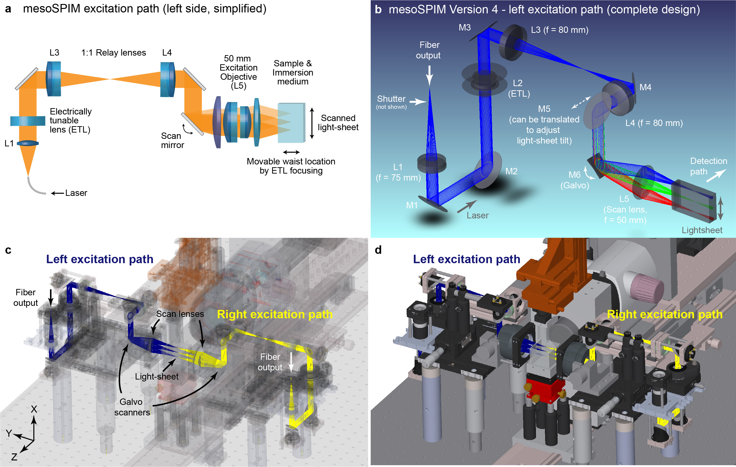 Optical design of the mesoSPIM excitation path. a) Simplified optical
path: Laser light from a single-mode fiber is collimated and then sent to an electrically tunable lens (ETL). The ETL is placed in the conjugate pupil of the galvo scan mirror via a 1:1 relay system (4f system) composed of two achromats (L3 and L4). The galvo scanner creates the light-sheet in combination with a f = 50 mm scan lens. The location of the light-sheet waist along the excitation
direction can be changed by changing the ETL focus. b) Full design of the left excitation path showing additional fold mirrors which were required to place the ETL in a vertical section of the optical path to avoid gravity-induced sag and to allow for adjustment of the light-sheet tilt using the translation of mirror 5 (M5). c) & d) CAD renderings showing how the left and right optical paths are placed inside the mechanical design.
Optical design of the mesoSPIM excitation path. a) Simplified optical
path: Laser light from a single-mode fiber is collimated and then sent to an electrically tunable lens (ETL). The ETL is placed in the conjugate pupil of the galvo scan mirror via a 1:1 relay system (4f system) composed of two achromats (L3 and L4). The galvo scanner creates the light-sheet in combination with a f = 50 mm scan lens. The location of the light-sheet waist along the excitation
direction can be changed by changing the ETL focus. b) Full design of the left excitation path showing additional fold mirrors which were required to place the ETL in a vertical section of the optical path to avoid gravity-induced sag and to allow for adjustment of the light-sheet tilt using the translation of mirror 5 (M5). c) & d) CAD renderings showing how the left and right optical paths are placed inside the mechanical design.