mesoSPIM_initial_ETL_parameters
To achieve the thinnest possible lightsheet, the ETL parameters need to be set properly. For a given zoom and wavelength, there are 4 parameters: Left & right ETL amplitude and left & right ETL offset. For an explanation of the mesoSPIM waveforms, please visit the wiki page here. The mesoSPIM ETL configuration files are .csv files that contain these 4 parameters for all combinations of zoom & wavelength setting in your microscope.
❗ This procedure can take 120 minutes for first-time mesoSPIM users and around 30 minutes if you have optimized ETL parameters before.
- Choose one of the ETL config files, copy & rename it
- Delete all lines covering wavelengths you won't need. If you need entries different wavelength, copy & paste all the zoom values from another wavelength and change the wavelength designation. There are 11 zoom positions.
⚠️ Please make sure that the string for each wavelength (i.e. "515 nm") matches the wavelength in your microscope configuration file perfectly. - Use the immersion cuvette and immersion medium you are planning to use most often
- Use either an index-matched test sample (fluorescent beads in agarose) or a fixed and cleared tissue (e.g. mouse brain).
- Start imaging:
- Choose the correct longpass/bandpass filter to see fluorescence and block scattered light.
- Select a region inside your sample with the XYZ stages that almost fills your FOV.
⚠️ At high (>3.2x) zoom it can be beneficial to move the sample in the lateral direction so that the light-sheet has to pass through less tissue before arriving in the FOV. This means that at high zoom, the left light-sheet should be optimized in a region of interest in the left part of your sample and vice versa.
- Do the ETL optimization
- Select one lightsheet direction (left/right)
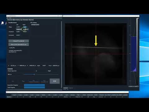
⚠️ Do not optimize ETL parameters with both light-sheets on, it can be very confusing! - Use the "Amp=0" buttons on the ETL tab to set the ETL amplitude of your selected direction to zero. The light-sheet waist should be visible either as the region with the fewest visible beads or a dark stripe (the zone of the least excited autofluorescence). ❗ If you can't see the waist, check the cuvette visually to localize the waist region. You might need to move the entire excitation path on its movable breadboard to center the waist region in the FOV.
- Change the ETL offset (i.e. by the scrollwheel of your mouse) and observe how the waist region moves laterally.
- Center the waist region on the vertical line of the crosshair in the camera window.
- Deselect the "AMP=0" button and optimize the ETL amplitude. This can be done by observing how sharp the outline of a cleared sample appears.
- Save the chosen parameters to the ETL config file.
- Select the other light-sheet direction and repeat the procedure (starting at step 1)
- Select one lightsheet direction (left/right)
- Repeat the procedure for every wavelength and zoom setting available in your system.
If you find it hard to see the beam waist then one possibility is to reduce the scanner amplitude until the brighter turn-around stripe is visible.
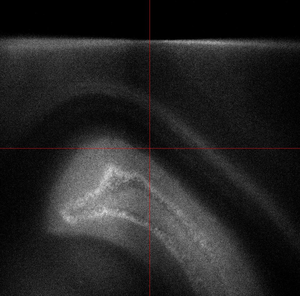
You will clearly see the beam waist with Amp=0 enabled.
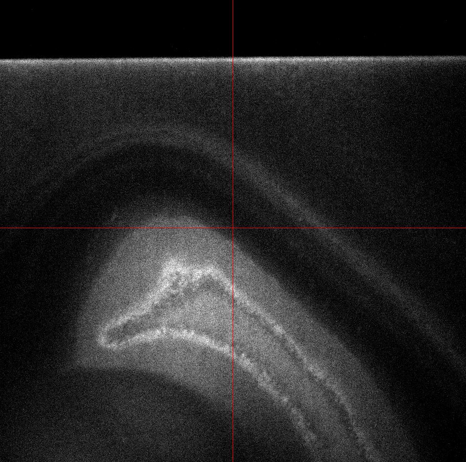
In the following image the beam waist is at the right location
When changing amplitude of the ETL sweep you can monitor the turnaround stripe and optimise for the most uniform looking stripe.
This is what it looks like when incorrect:

This is correct: