mdibl_alignment
This page describes the alignment procedure necessary when modifying a mesoSPIM V5 with the objective turret. Parts of this procedure might also be necessary. The version of mesoSPIM-control running this hardware has a variety of differences compared to the standard mesoSPIM software - make sure to have a closer look into the config file.
-
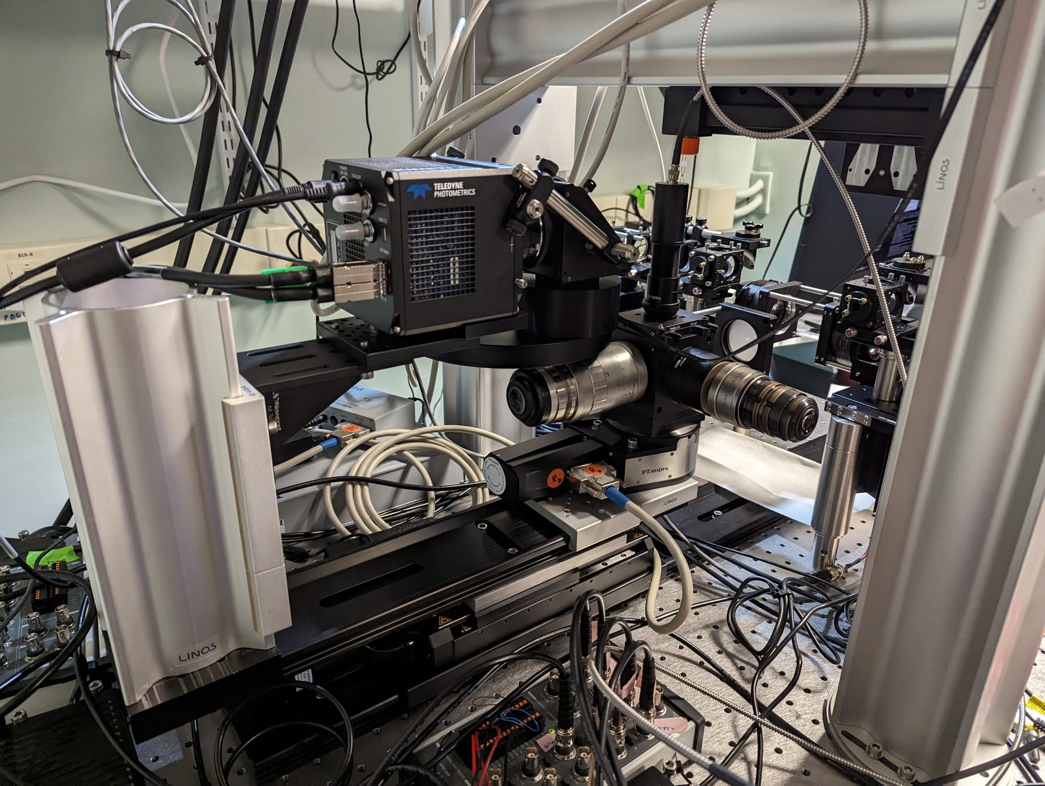
the excitation paths should be realigned after raising them using 30 mm spacers (P30/M):
-
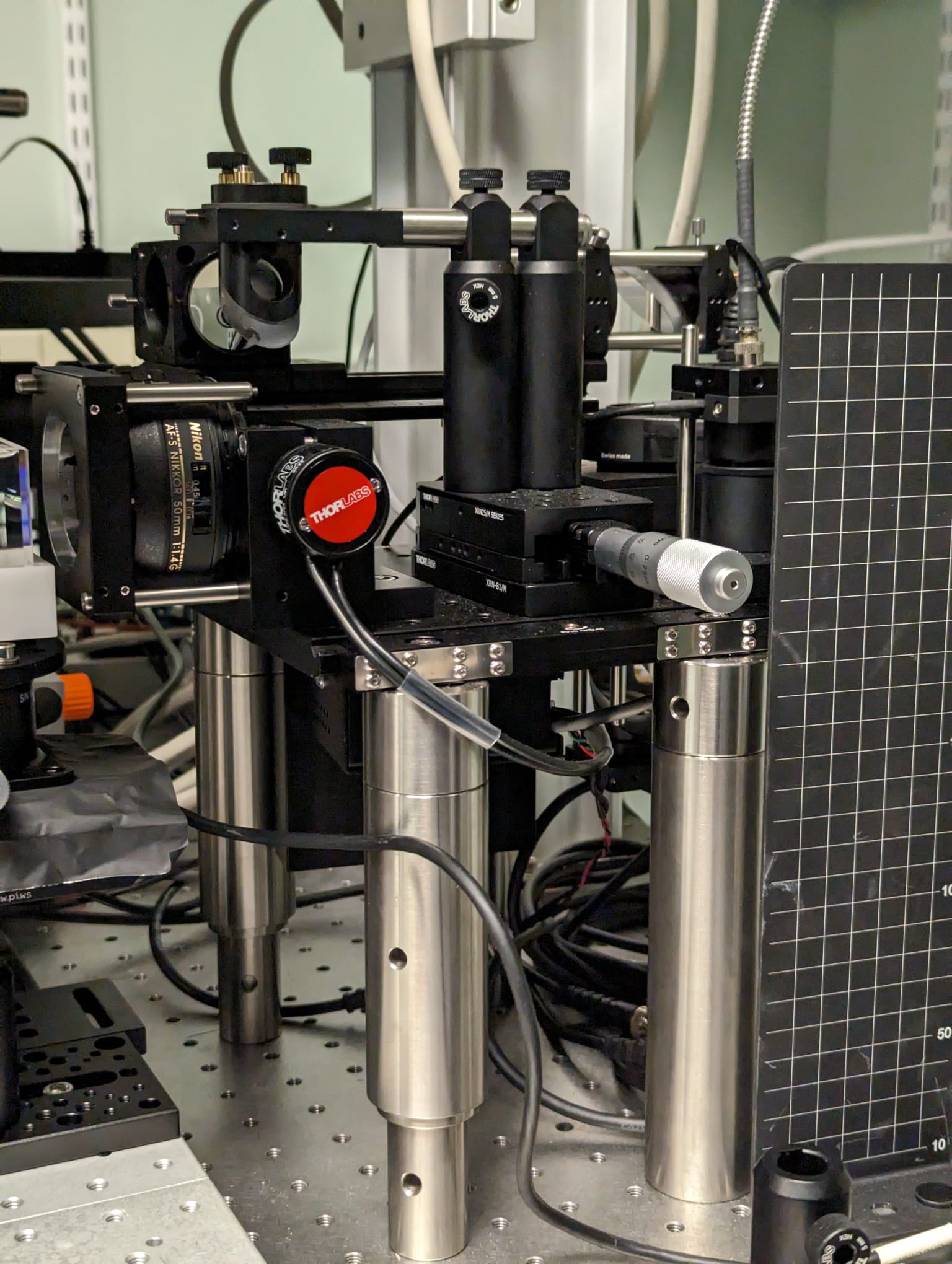
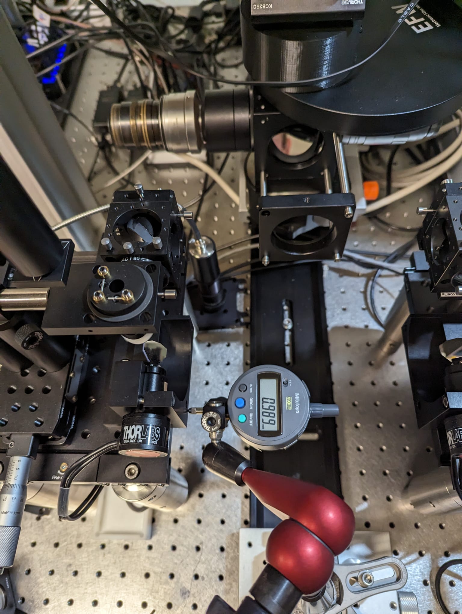
use a digital indicator to make the breadboards carrying the excitation paths parallel to the optical axis
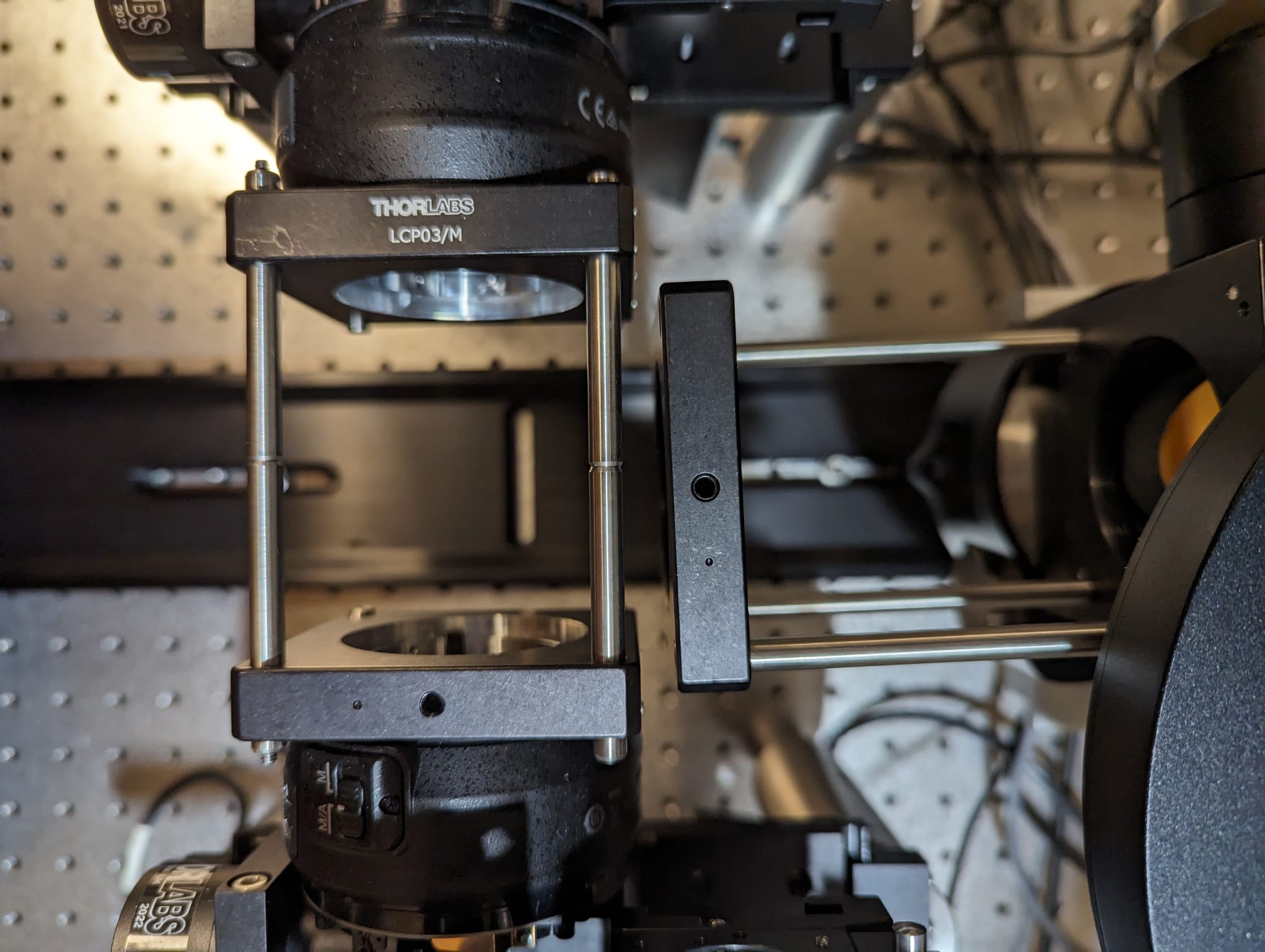
- before the foldmirror DM1 inside the turret can be adjusted, the correct angle needs to be found
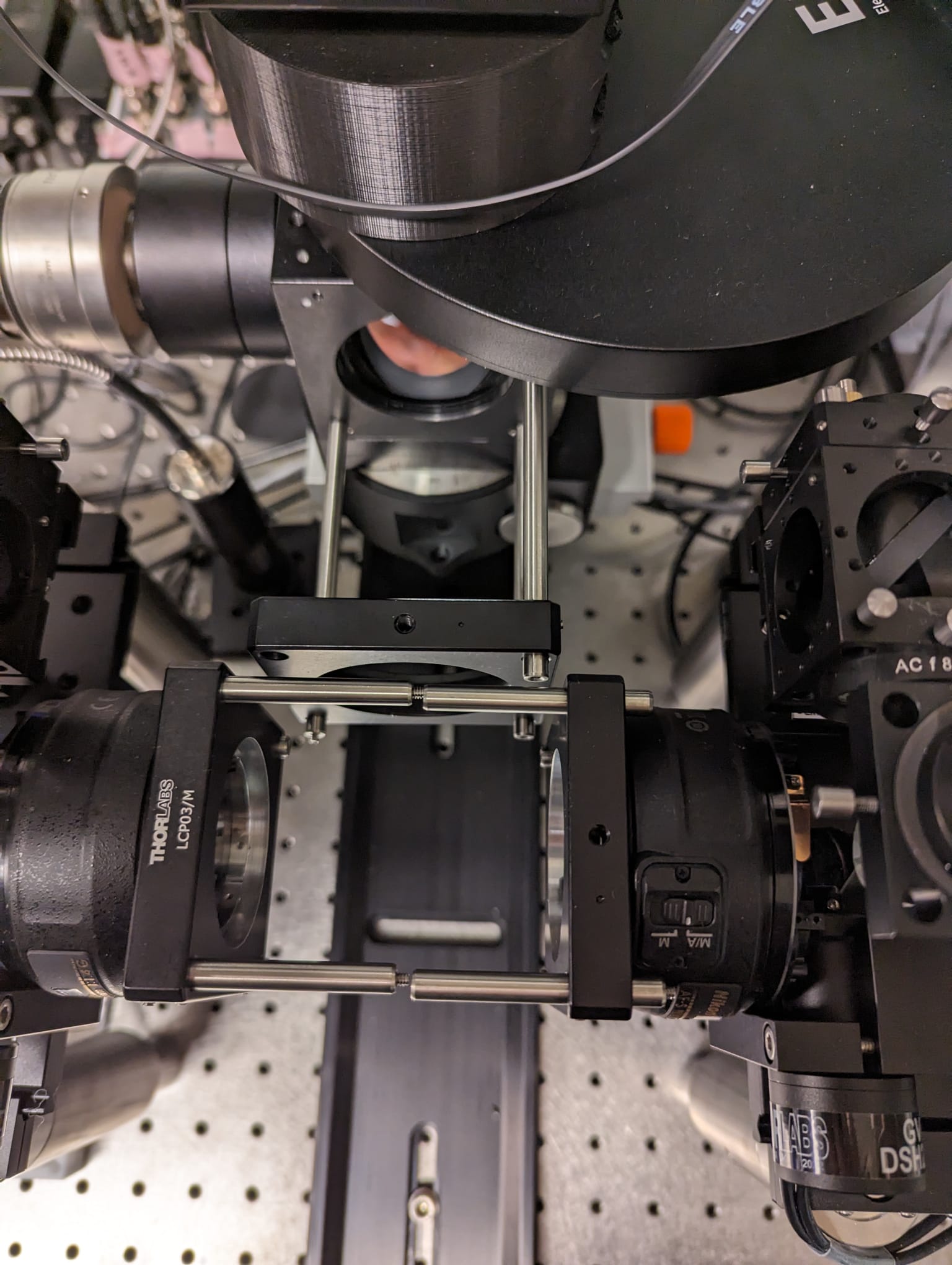
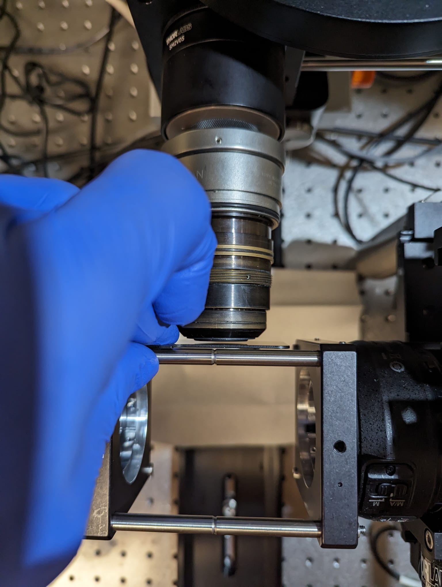
- attach long cage rods to the cube and attach a 60 mm cage plate to the front, attach
long rods bridging both excitation paths as a reference
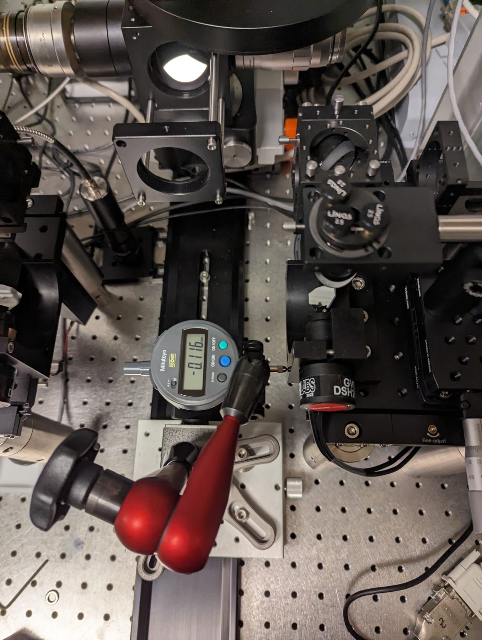
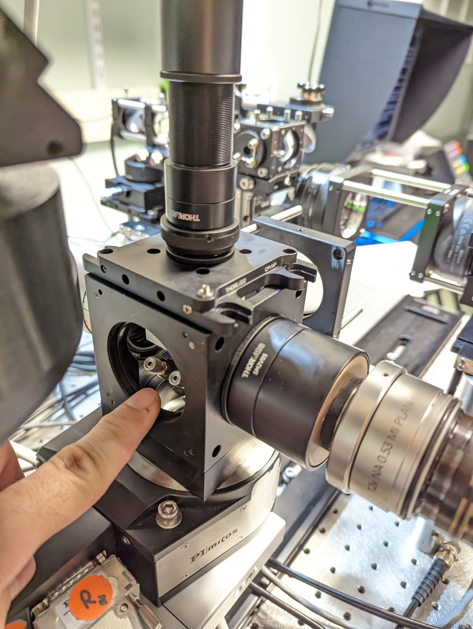
You can move the sample XYZ stage assembly out of the way
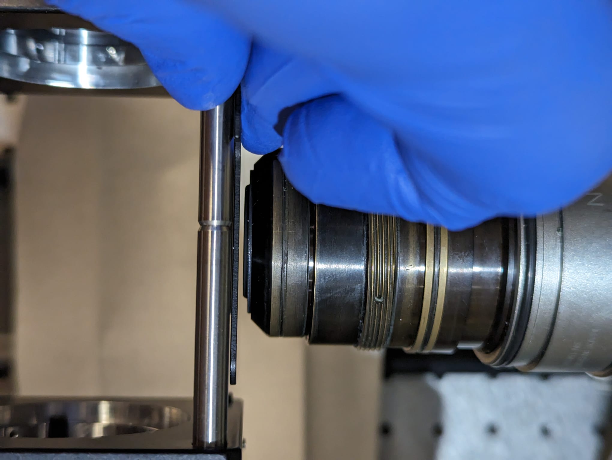
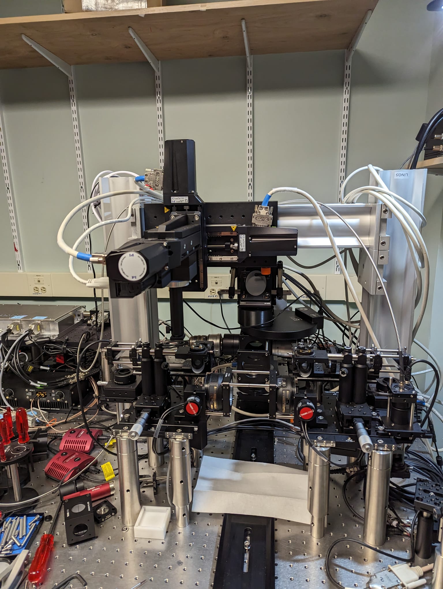 Move the focusing stage carefully as possible such that the cage plate almost touches the
rods connecting both excitation paths. Angular misalignment shows up as a gap with varying
thickness
Move the focusing stage carefully as possible such that the cage plate almost touches the
rods connecting both excitation paths. Angular misalignment shows up as a gap with varying
thickness
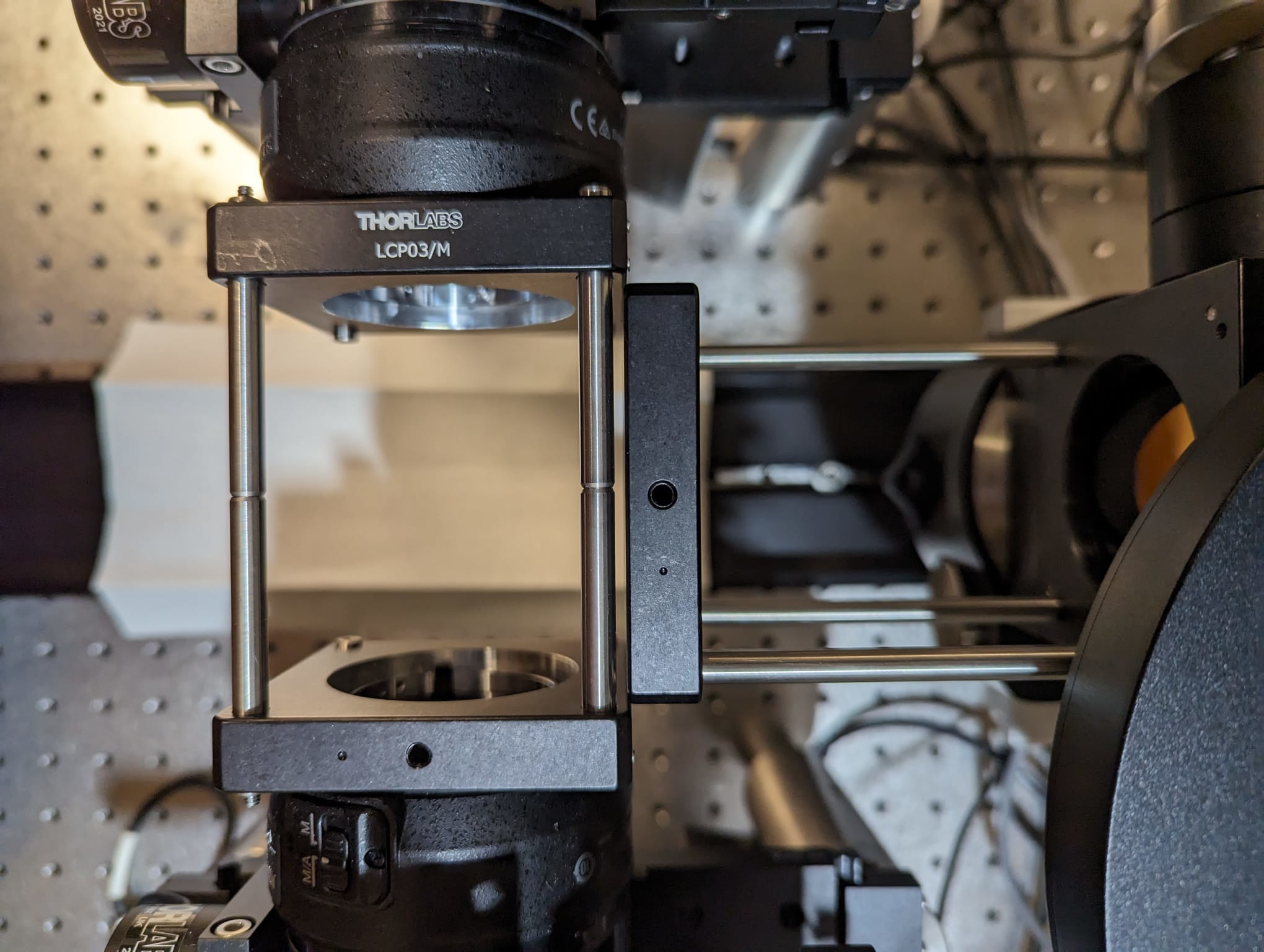
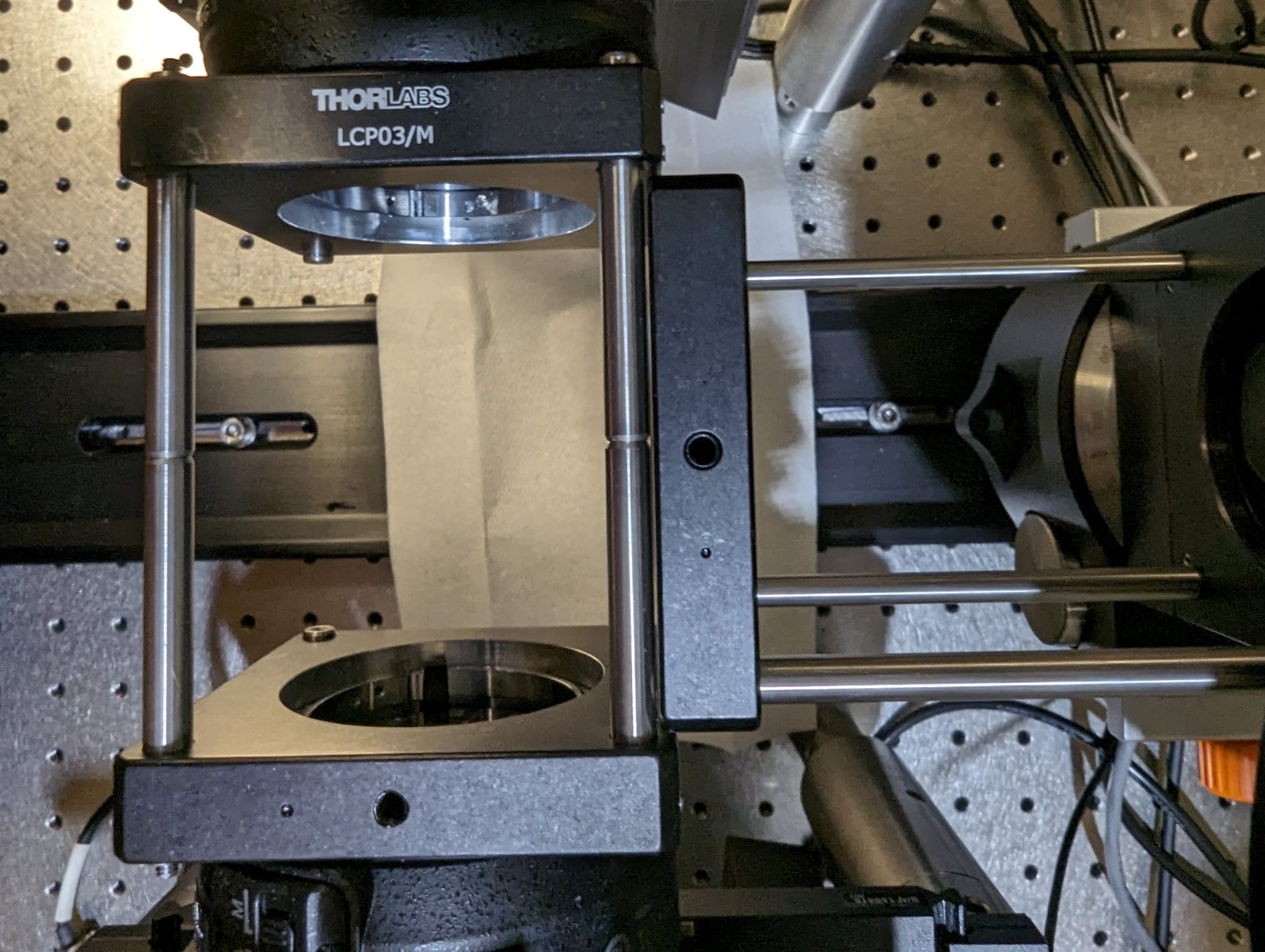 After finding a good rotation angle, you can check with the 12x objective
- update the config file with the turret positions based on your measured angle in increments of 90 deg (e.g. when setting up the MDIBL mesoSPIM, the alignment position was at 2 degrees, and the objectives are at 92, 182, and 272 degrees)
- the mirror inside the rotating objective turret cube is Detection Mirror 1 (DM1)
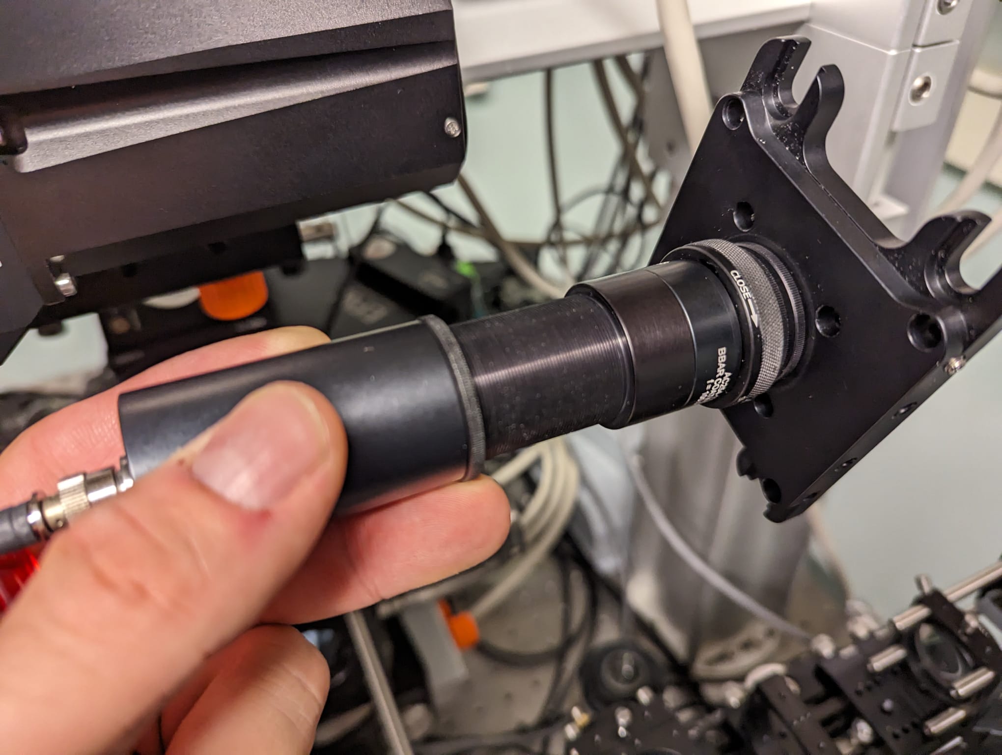
⚠️ make sure that the rotation alignment is complete before doing this step -- otherwise, the mirror will be set to an incorrect position- attach a beam collimator to the top of the objective turret via a 60 mm -> 30 mm cage adapter. You can use the adapters from an excitation path (realignment will be necessary afterwards)
- attach a cage system to the front (similar as for the rotation alignment)
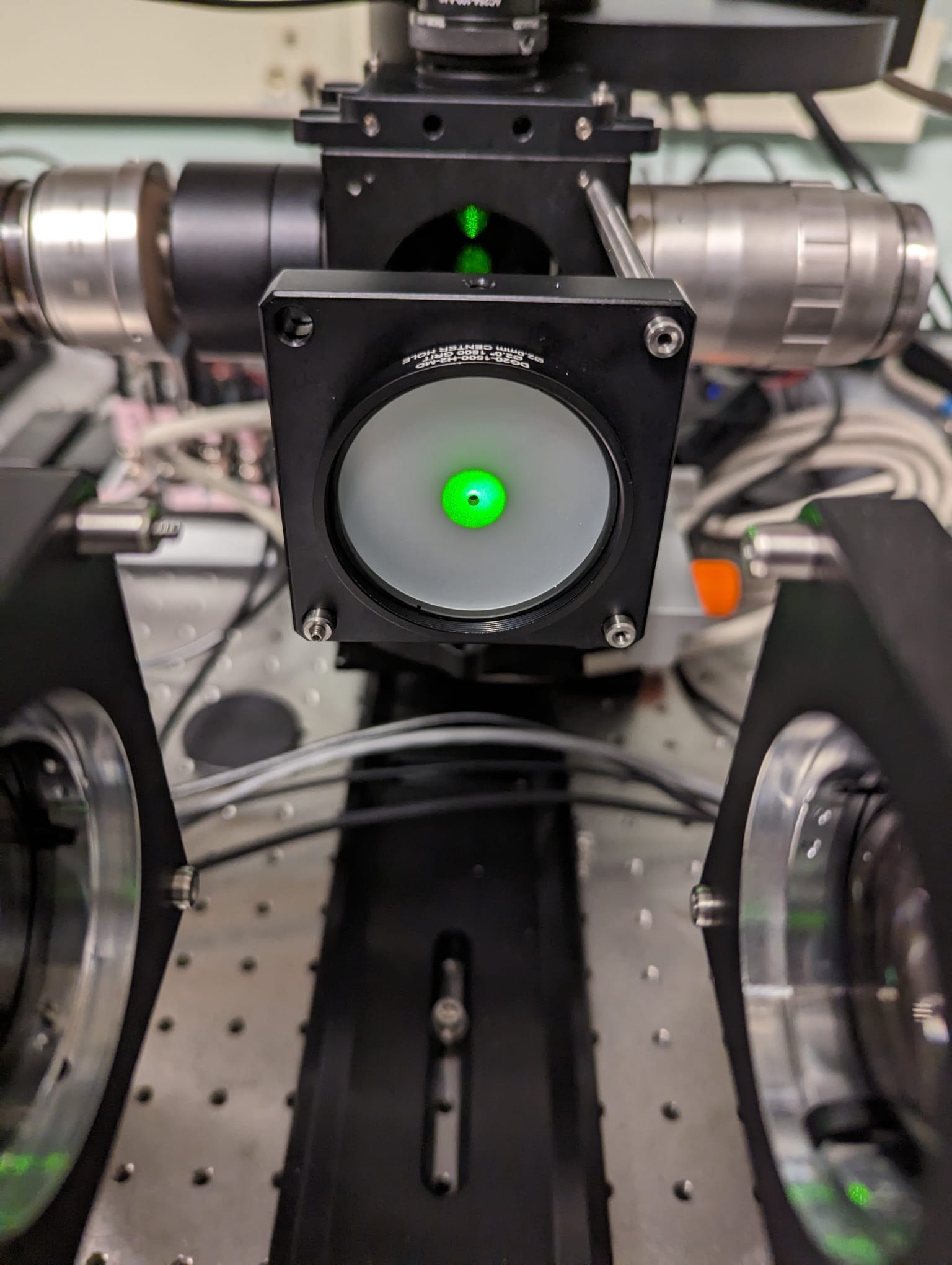
 You can move the camera assembly to the rear and the stages to the side:
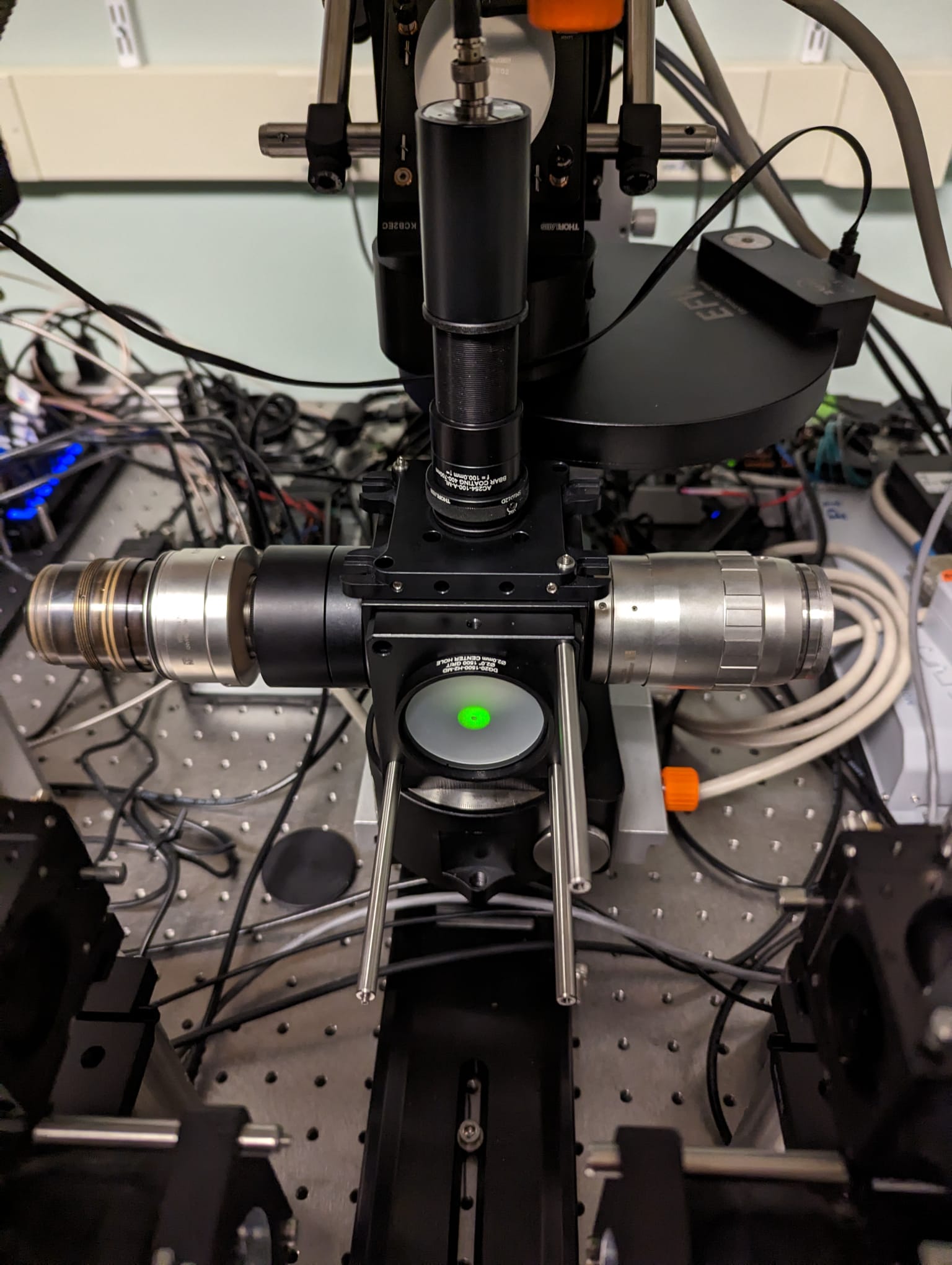
Use the tip/tilt mirror mount screws to center the reflection on a diffusor plate:
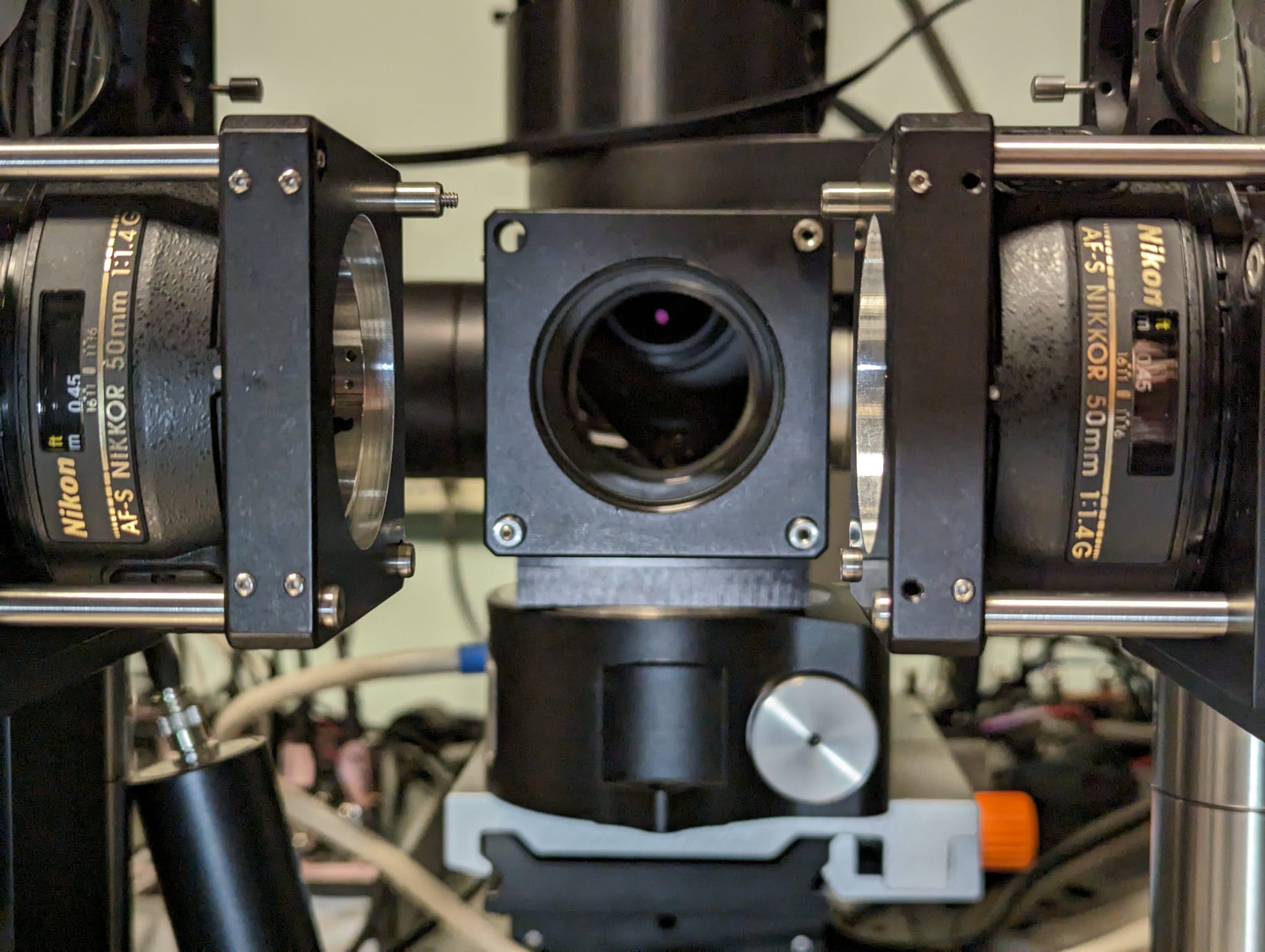
Aim down the 60 mm cage plate and cube SM2 apertures to see where the detection tube lens is located relative to the apertures. This is the view when you are not aiming along the axis of the SM2 threads:
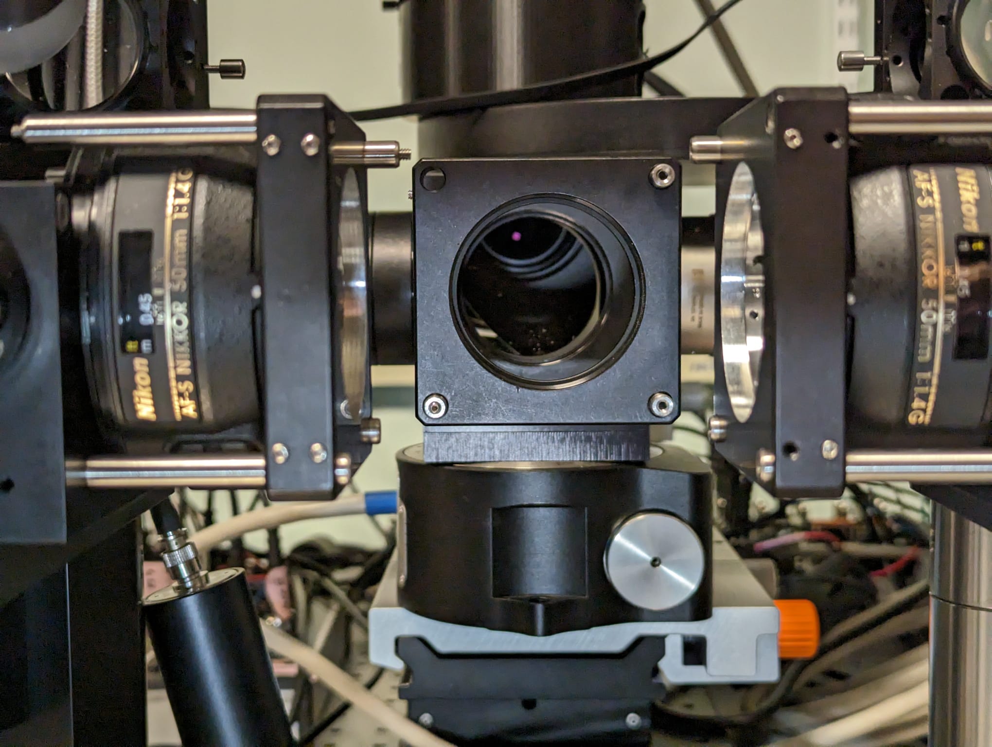 This is the view when viewing correctly - the tube lens is decentered as the camera
assembly is placed incorrectly.
This is the view when viewing correctly - the tube lens is decentered as the camera
assembly is placed incorrectly.
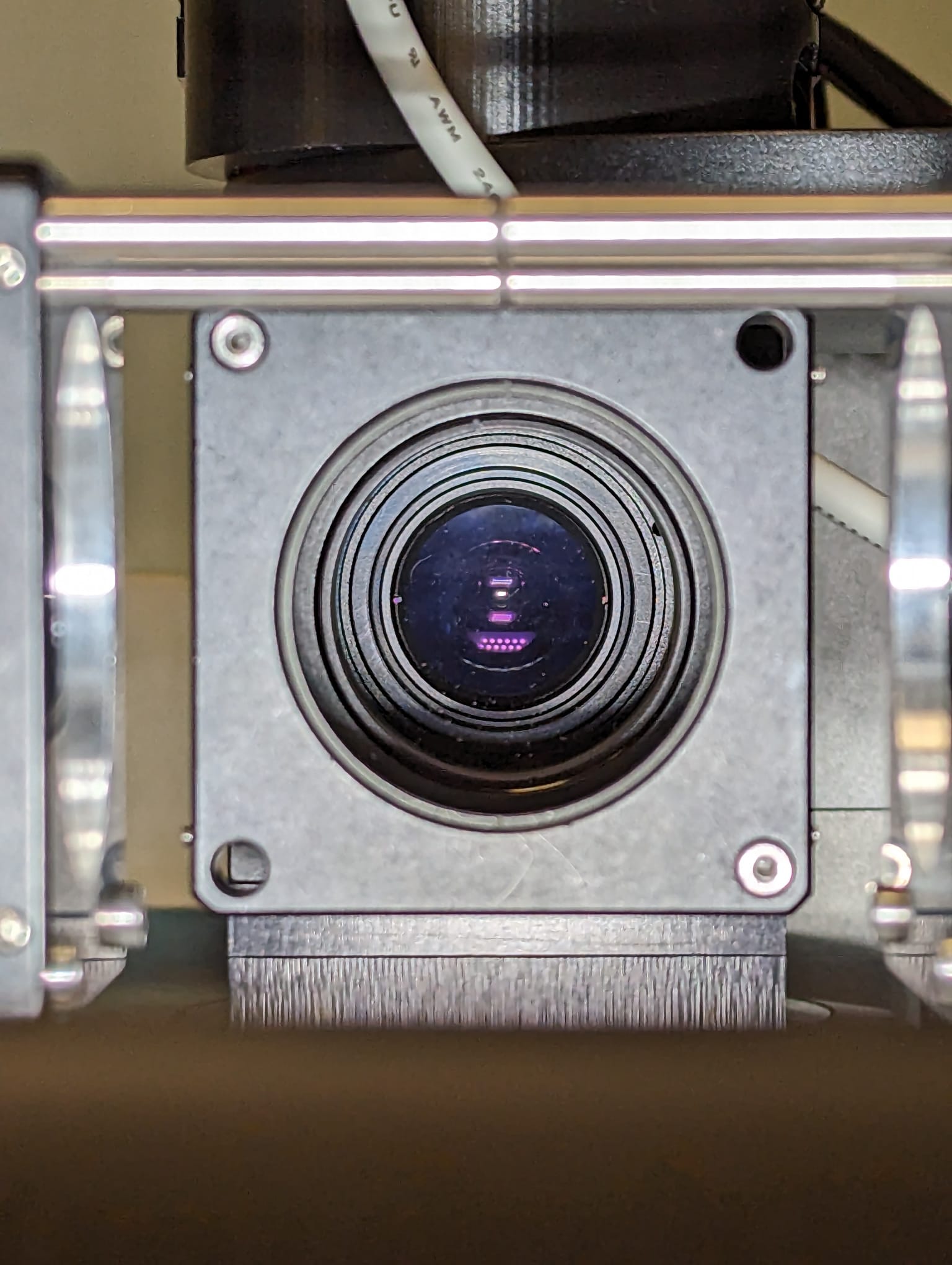
 After moving the camera & fold mirror & tube lens it should look like this:
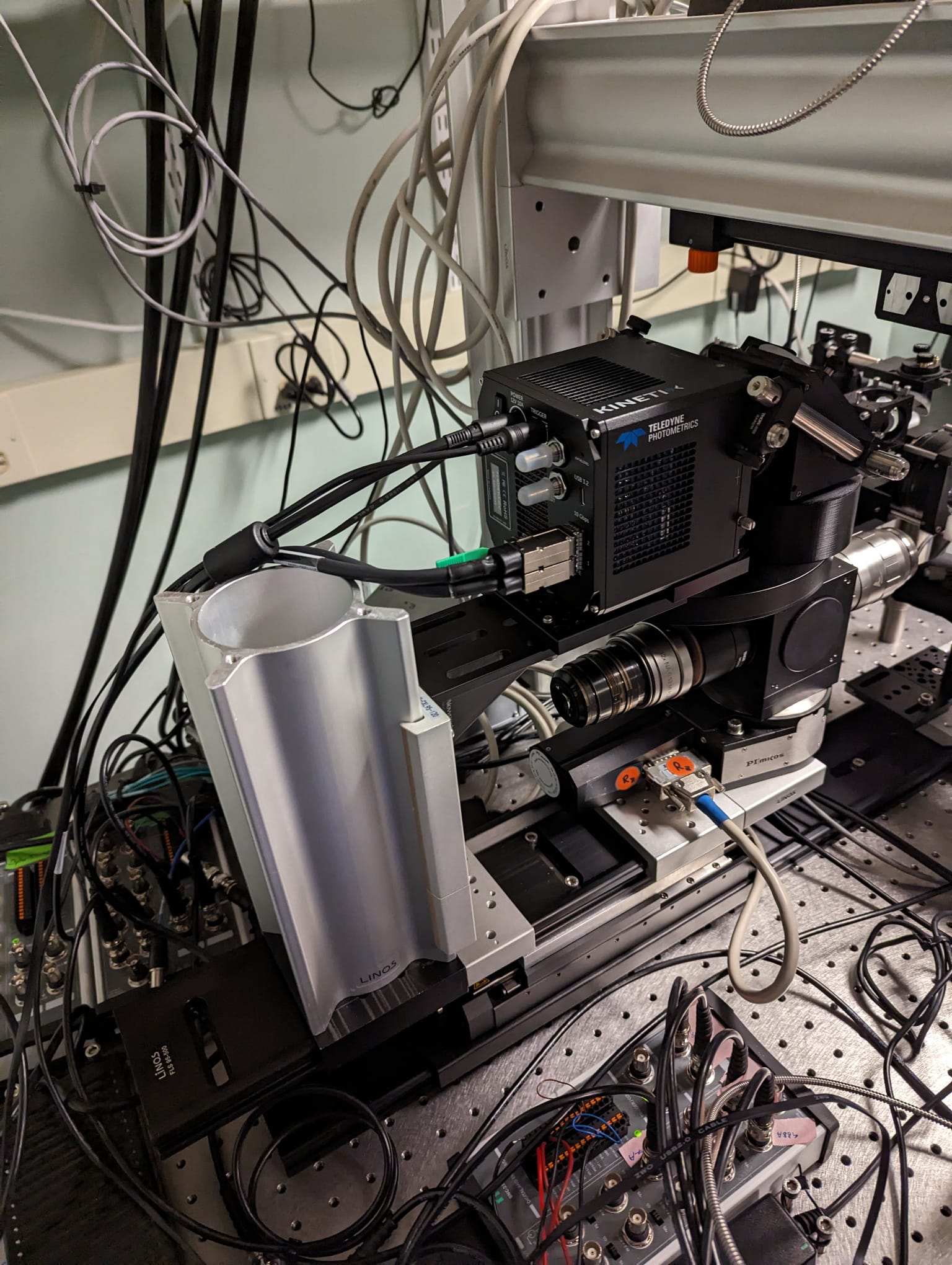
 Externally, the detection path looks like this:
- the other 2" fold mirror is DM2
- freeze the galvos (ETL tab in mesoSPIM-Control) and align the galvo offset such that the beam is in the center of the objective front lens aperture (when viewing the objective through the immersion cuvette filled with a medium) with either the 4x or the 12x objective
- alternatively, set the offset to 0 and rotate the galvos in their mounts
- optimize ETL parameters if necessary (such that you have a nice thin line across the camera image)
- afterwards, use the DM2 vertical adjustment to center the beam on the horizontal red line in the mesoSPIM-Control camera window
- set ETL amplitude to 0 and visually position the focus in center of the objective front lens
- use DM2 horizontal adjustment to center the beam waist on the crosshairs in the mesoSPIM-control camera window
- The M-406.4PD focus stage is positioned such that the objectives are in focus at stage positions around 85000 micron (this is to have lots of space for backward movement for the objective turret rotation)
Aspects of daily operation (ETL parameters, cuvette tip/tilt and cuvette position adjustment / "motorized correction collar" ) are described on a dedicated page