mesoSPIM_scanlab_galvo_upgrade
Several exisiting mesoSPIM V4/V5 were upgraded with Scanlab Dynaxis 14/1 scanners in 2019. This document provides an overview of the necessary modification steps.
Using larger scanners has the following advantages:
- with 14 mmm scanners, a higher excitation NA (0.15) can be achieved. Compared to the NA 0.1 beam provided by Thorlabs 10 mm, both the axial resolution and shadow reduction are improved
- the galvos can be run at 200 and 400 Hz
However, there are several challenges as well:
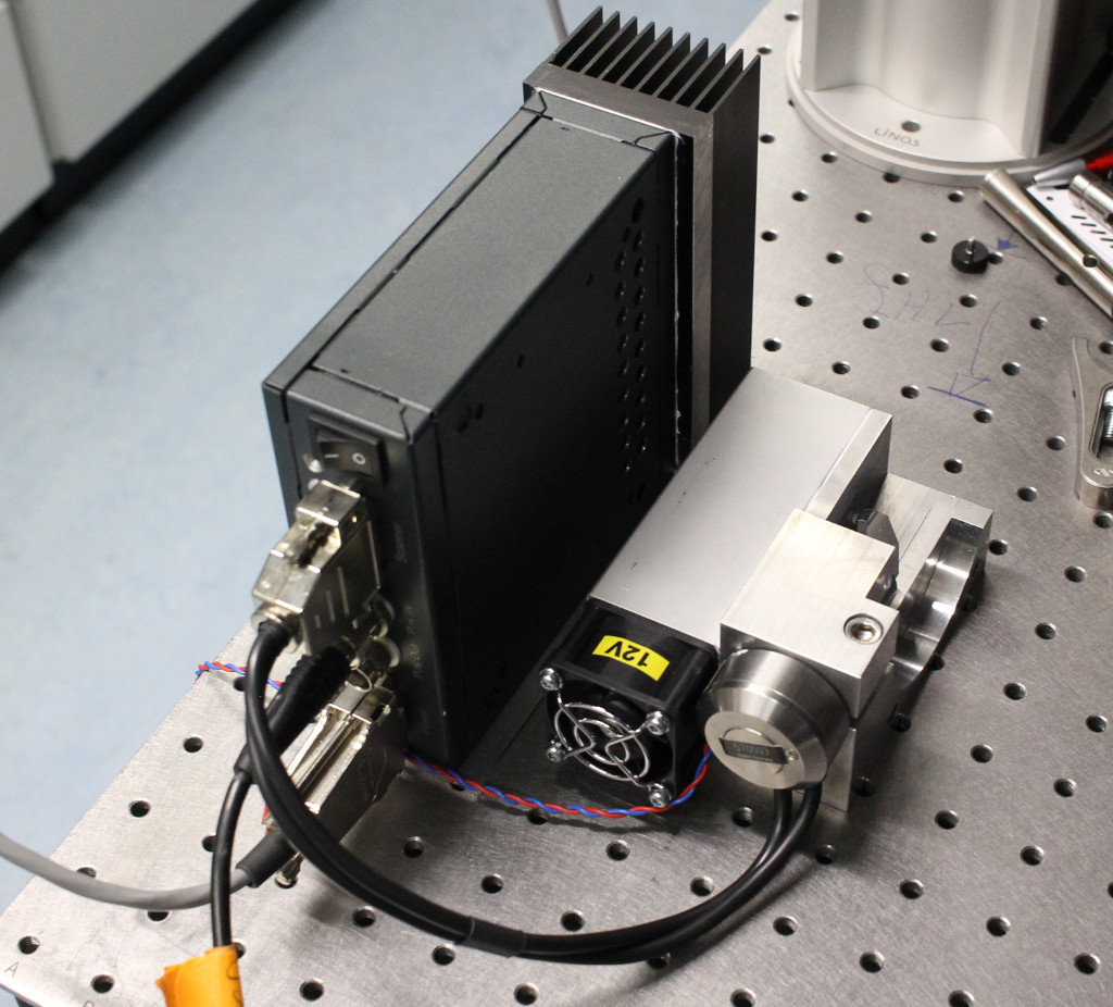
- while testing early versions of the Scanlab galvos with the mesoSPIM, we had problems with overheating of the galvo power supplies (Thorlabs GVS011), Scanlab driver boards and scanners themselves. We therefore added fans to all components
- 2x sets of:
- Scanlab galvo mounts (left & right)
- Scanlab scanners (Dynaxis 3M)
- Custom scanner drivers
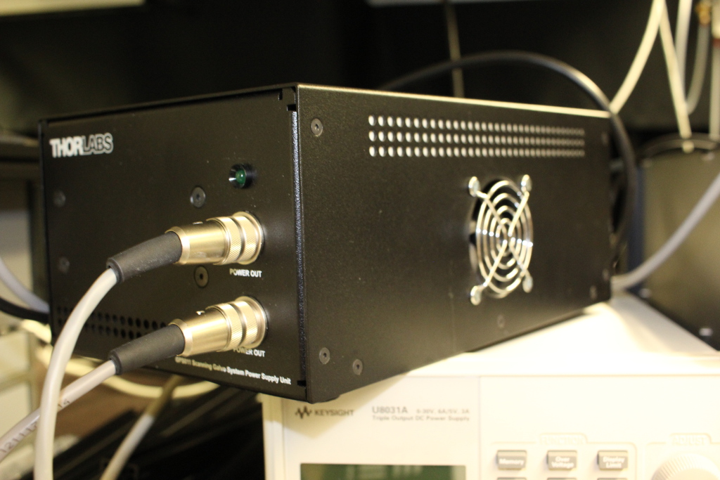
- Modified Thorlabs power supplies (GPS011EC)
- 2x Thorlabs 50 mm 12.7 mm posts
-
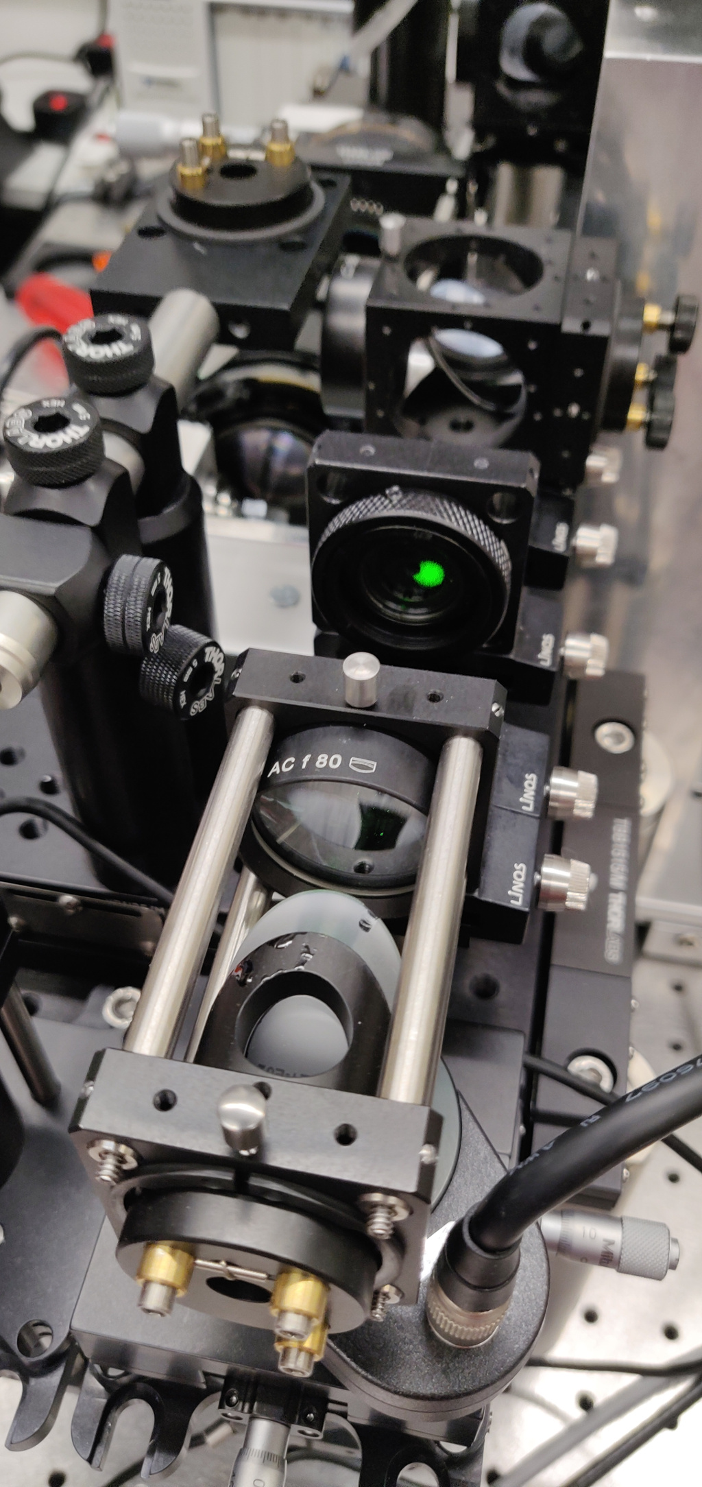
Alignment tools to realign an excitation path
- Shear plate
- alignment collimator
- Position indicator
- Adjustable arm
The Scanlab mirror mounts are larger than the Thorlabs scanner mounts. This means that a slight rearrangement of the excitation path is necessary.
- remove the old (Thorlabs or other manufacturer) scanner & scanners
- remove the linear stage & its baseplate
- remove the rail carrying the relay lenses
- remove the inner 50 mm post
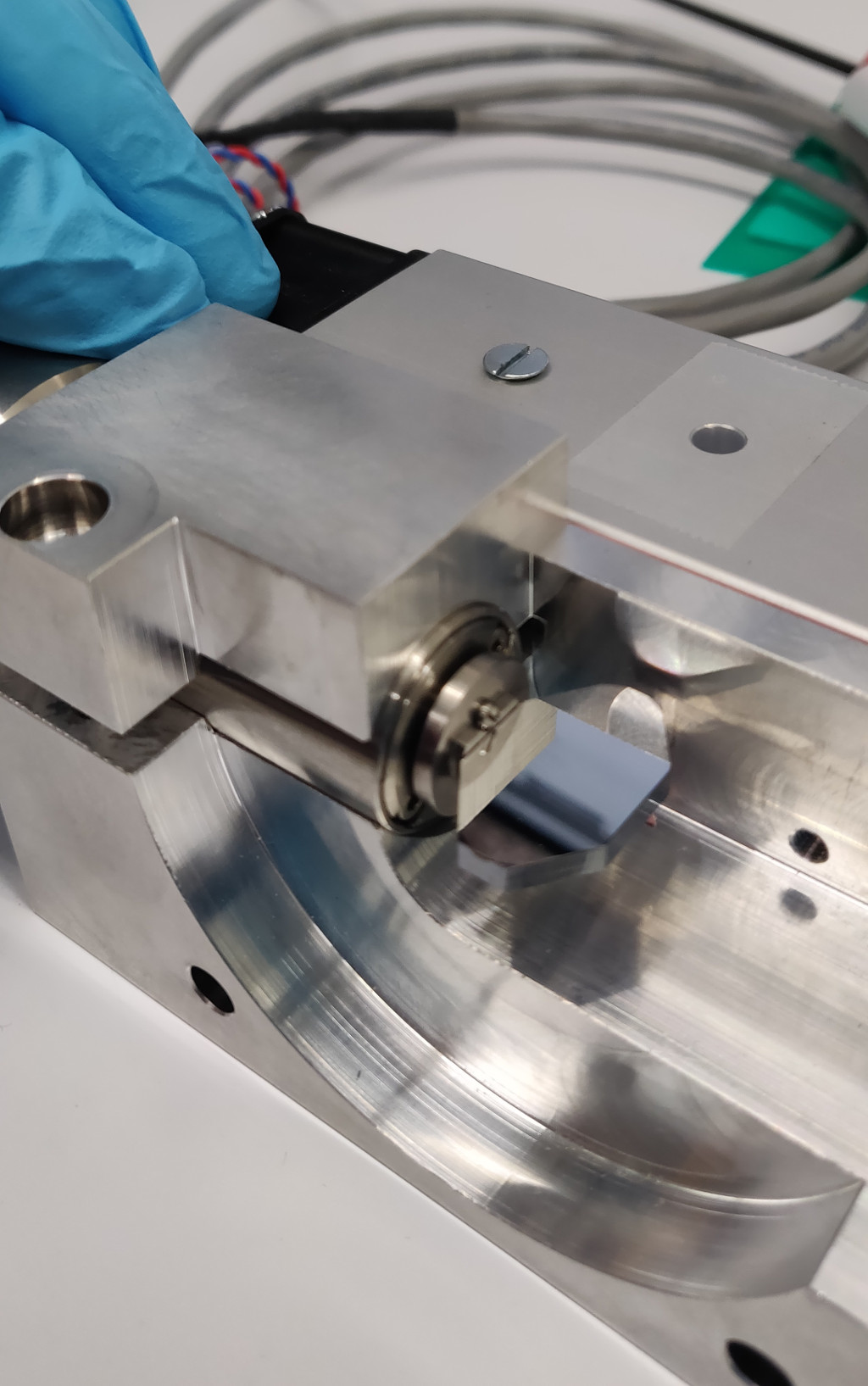
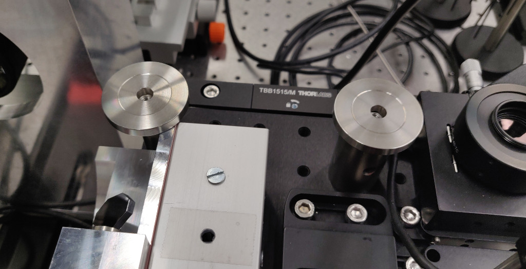
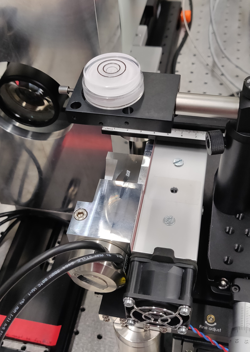
After clearing the excitation breadboard place the galvo mount according to the picture. Use two screws to fasten the scanner mount to the raised breadboard. Gently tighten one of the screws and leave the other untightened. The tighter screw will be used as a pivot point while making the scanner mount parallel to the detection axis/rail. To do this, place a position indicator on a FLS95 carrer (ideally using an articulated arm) and indicate against the front surface of the galvo mount. Make sure that the movable indicator does not drop into the holes for 60 mm cage rods which will later be used to mount the scan lens.
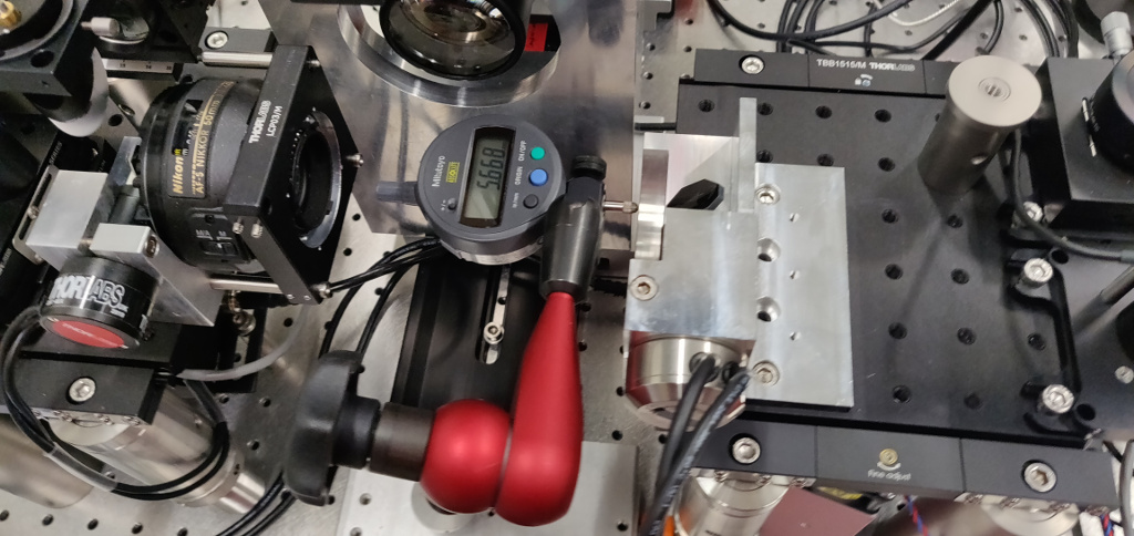
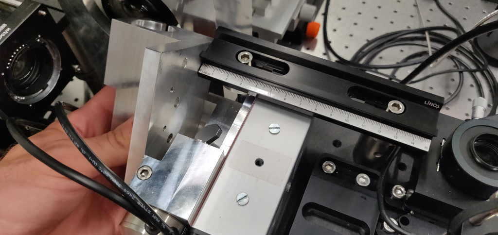
Slide the indicator back and forth to measure the position difference along the front surface. Gently tap the scanner mount to make the scanner mount as parallel as possible. A position delta of <30 microns is usually sufficent. In this example, the delta is <5 micron. Gently tighten the screws while watching the position readout to avoid any last-minute deviations.

Place the baseplate for the linear stage according to the picture.
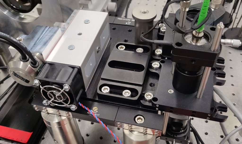
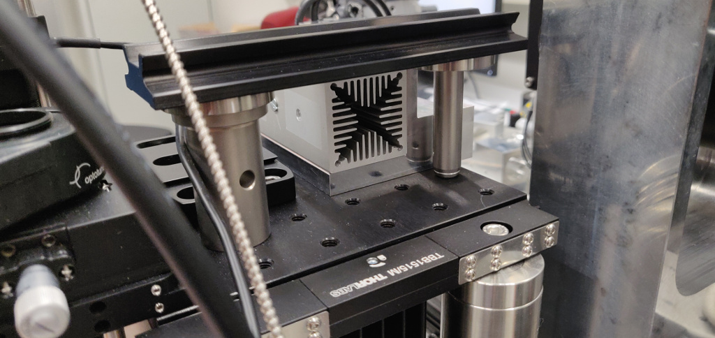
The raised FLS40 rail is usually placed on two 1-inch 50 mm posts. The airflow from the scanner fan would strike this post and heat it up. Therefore, the inner post is replaced with a 12.7 mm 50 mm post. As the 1.5 inch spacers used to mount the FLS40-rail have an indentation in the center, an additional washer is necessary to approximately compensate this offset. Use a M4-set screw and a M4-M6 thread adapter to modify the M4-tapped side of the post. The M6-tapped end will be used to mount the raised FLS-40 rail.

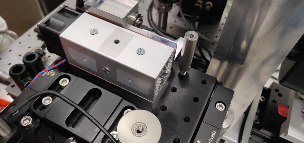
Place this post as shown in the following picture.
Add two 1.5 inch spacers with 5 mm thickness to each post.
Mount the FLS40 rail on top. Use a flat part (another galvo mount, a spare breadboard etc.) to make the rail parallel the galvo mount before tightening the screws.
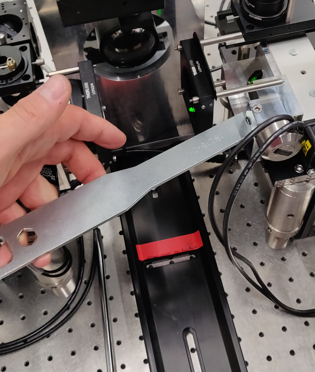
The post was replaced and shifted to allow the hot air from the galvo fan to
clear the posts carrying the rail.
Mount the linear stage on the baseplate an add the M5 assembly (two 75 mm posts,
90-degree post adapters, etc.) You will need to replace the 75 mm post carrying M5
with a 100 mm-post.
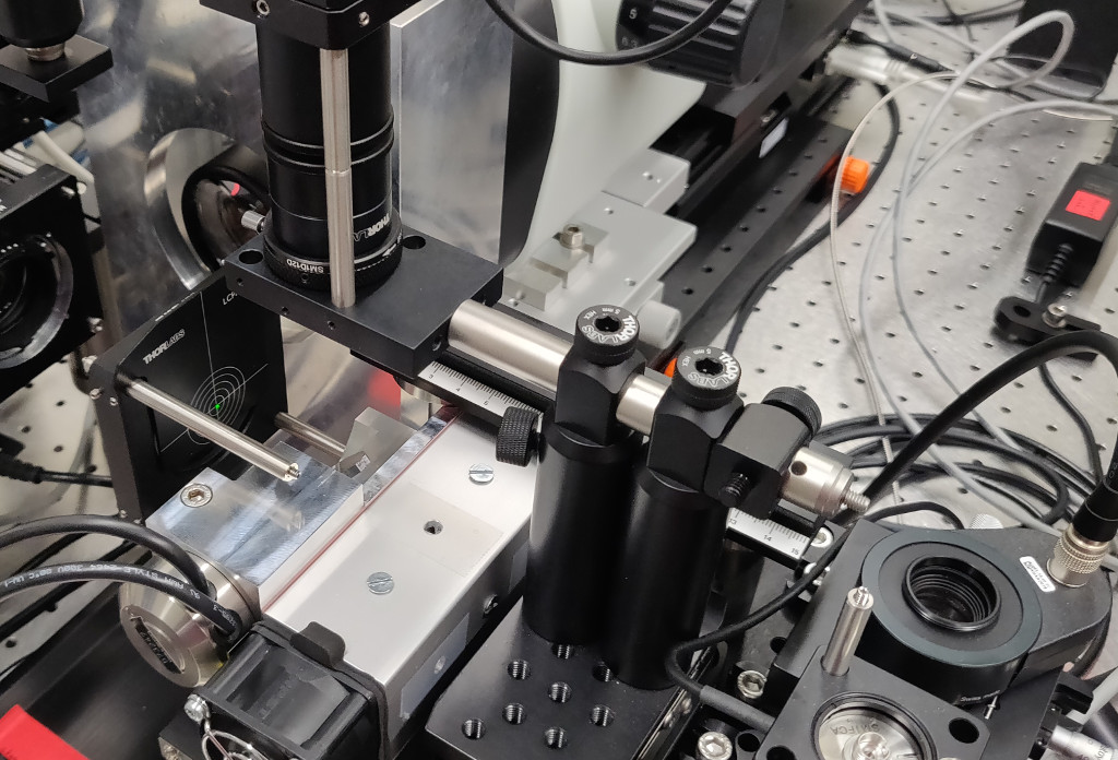
Use a water level to level the mirror mount.
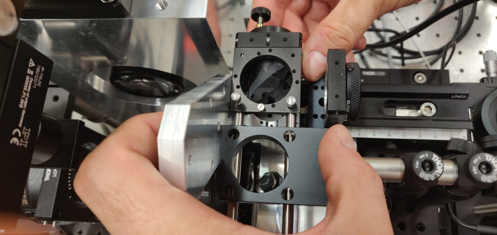
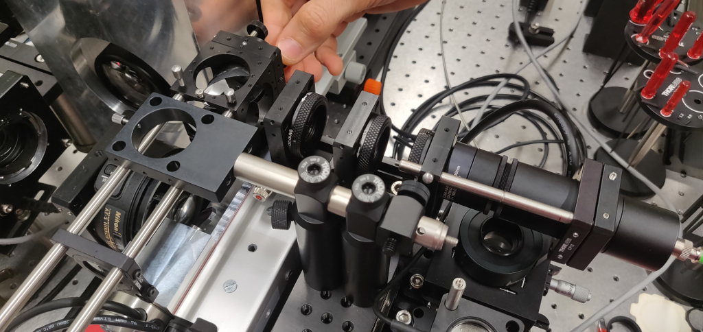
The remaining steps are similar to the standard excitation path alignment. The following photos are for reference only.
Using a 60 mm alignment target and an alignment collimator to adjust the galvo rotation.
Inserting the M4 fold mirror.
Aligning M4 by adding an alignment collimator on the FLS40 rail.
Coarse M5 alignment
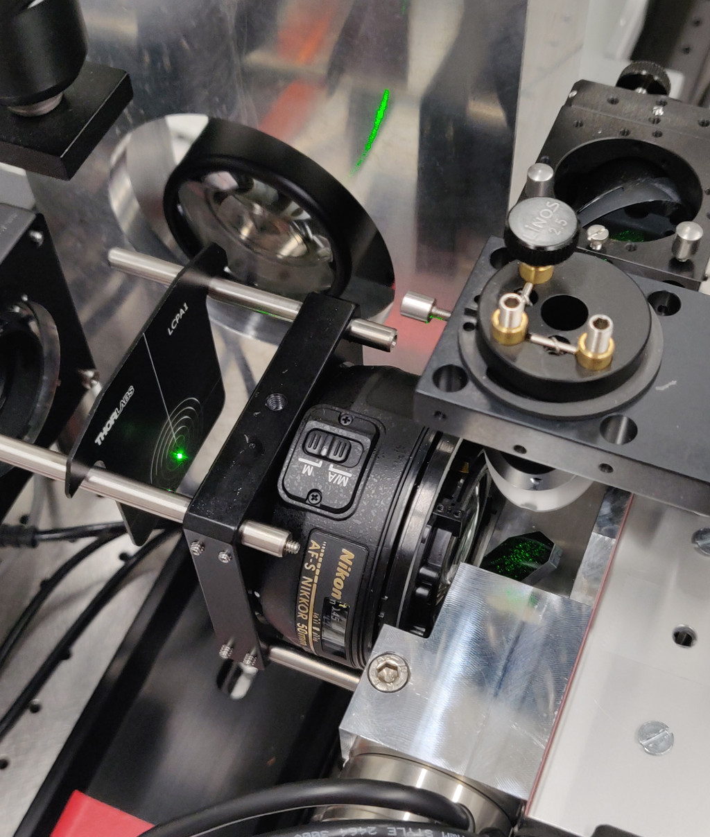
M3 alignemnt