Repository navigation
"DXF" in QET means two unrelated features that happen to share a file format:
| Direction | Where | How | |
|---|---|---|---|
| Export | sheet → .dxf
|
File → Export, alongside PDF/PNG/SVG | in-process, QET's own code |
| Import |
.dxf → element geometry |
the element editor's Import a DXF file | shells out to a separate third-party program |
They don't round-trip each other and aren't part of the same code path. If you're looking for "import a DXF drawing as a sheet", that isn't what either of these does — see §3.
Source: sources/createdxf.{cpp,h}, sources/dxfpaintdevice.{cpp,h},
sources/dxfexport.{cpp,h},
sources/dxf/dxftoelmt.{cpp,h}.
File → Export, same dialog as PDF/PNG/SVG, one .dxf file per sheet. The
border, title block and every diagram item on that sheet are included.
It also runs from the command line, like the PDF, PNG and SVG exports.
qelectrotech --export-dxf myproject.qet out/
qelectrotech --export-dxf myproject.qet out/ --show-terminals
qelectrotech --export-dxf myproject.qet out/ --dxf-blocks
qelectrotech --export-dxf myproject.qet out/ --dxf-attributes-
One file per sheet, named like the PNG and SVG exports: the sheet
number on two digits, then its title —
01_General.dxf,02_Macro 3.dxf. The output folder is created if it does not exist. - The same file the Export dialog writes, with the dialog's default options, which come from the export settings in the preferences (border, title block and so on). Given the same settings, the two are byte-identical. The column numbers across the top border follow the preference that starts them at 0 or 1, so a machine with a different setting gives a different border.
-
--show-terminalsdraws the terminals, as the dialog's option does. -
--dxf-blockswrites each symbol as a DXF block, and--dxf-attributesalso turns the symbols' texts into block attributes; see Symbols as blocks below.--dxf-attributeson its own implies--dxf-blocks. Without either flag, the two options keep the value saved in the preferences (both off unless you changed them). - Pictures become outline boxes, as in the dialog (see below), and a note is printed saying so.
-
Scripts run with
--runget the same export asqet.exportDxf(outDir, showTerminals)— see JavaScript Scripting.
Exit codes are the same as the other exports: 0 success, 1 the export
failed (for example, the output folder cannot be written), 2 called wrongly.
Two exports of the same sheet give identical files, so a DXF can be compared with an earlier one to see what changed. (Before PR #1075, every export wrote its entities in a different order.)
Each kind of content goes on its own layer, so a CAD program can tell the border from the wires. (Before PR #1079, everything sat on layer 0.)
| Layer | What is on it |
|---|---|
QET_BORDER |
the sheet frame, with its column and row headers |
QET_TITLEBLOCK |
the title block |
QET_SYMBOLS |
the drawing of each symbol |
QET_SYMBOL_TEXTS |
texts belonging to symbols: labels and the like |
QET_TERMINALS |
terminal markers, only when terminals are drawn (--show-terminals or the dialog option) |
QET_WIRES |
the wires |
QET_WIRE_NUMBERS |
the texts on wires |
QET_JUNCTIONS |
junction dots |
QET_TEXTS |
free texts |
QET_XREFS |
cross-references: contact tables beside a master, labels beside a slave |
QET_SHAPES |
lines, rectangles, ellipses and polygons drawn on the sheet |
QET_TABLES |
tables such as the parts list |
QET_IMAGES |
the outline boxes that stand in for pictures |
The names are fixed and English, whatever language QElectroTech runs in, so
a CAD user's layer filters and scripts keep working. The QET_ prefix keeps
them together in the layer list and apart from the receiving drawing's own
layers.
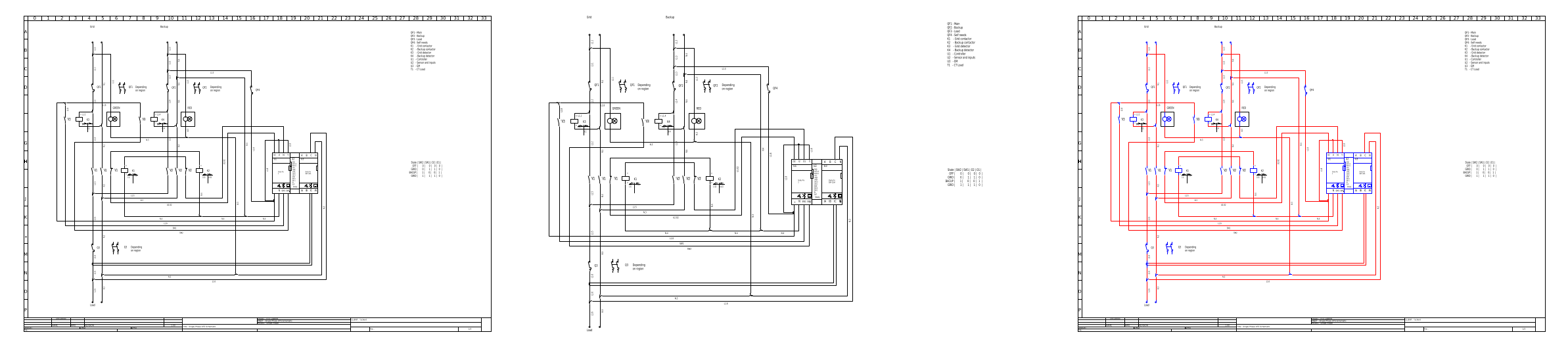
2612_ats_singlephase.qet, sheet 1, exported with this change and rendered
with ezdxf. Only layer settings in the viewer differ between the three.
Colours. Where QElectroTech sets no colour of its own, entities take their layer's colour (BYLAYER), so recolouring a layer in the CAD program recolours everything on it. The file still looks the same when opened, since every layer starts white on black, black on white. Wires keep the colour they have on the sheet: until this change every wire was exported in the default colour, and 723 of the 3,190 wires in the example projects lost theirs. A two-colour wire gets its main colour.
What does not change: the lines themselves, their positions and the DXF version. Only the layer each entity is on and its colour code differ from an older export.
Not included yet: an option to put everything back on layer 0, and dashed wires (they come out continuous).
By default every symbol is exported as loose lines, arcs and texts: in a CAD program, selecting a contactor means picking each of its lines. Two options in the export dialog change that. Both are off by default, and with both off the file is the same as before they existed.
| Option in Fichier → Exporter (File → Export), format DXF | Command line | Effect |
|---|---|---|
| DXF : symboles en blocs (DXF: symbols as blocks) | --dxf-blocks |
each symbol becomes one DXF block, placed with an INSERT
|
| DXF : textes des symboles en attributs (DXF: symbol texts as attributes) | --dxf-attributes |
the symbol's own texts become attributes of its block. Can only be ticked when the first option is |
The two labels are not translated yet, so the English interface shows them in
French as above. They are in the Options de rendu (Rendering options) box
of the export dialog, and on the Export page of the preferences, where they
set the default for the dialog and for --export-dxf.
Symbols as blocks. Each symbol definition a sheet uses is written once, as
a block, and every placed symbol is an INSERT of that block, carrying only
its position and its quarter-turn. A CAD program then selects, moves, counts
and replaces a symbol as one object, and its block list shows which symbols the
sheet uses.
-
Block names come from the symbol's file name, in capitals, with
QET_in front:contacteur.elmtgivesQET_CONTACTEUR. Characters DXF does not allow in a name become_, names are cut at 31 characters, and two different symbols that end up with the same name get_2,_3… Repeat exports give the same names, so two exports of an unchanged sheet are still identical. -
The lines inside a block keep their layers (
QET_SYMBOLS,QET_SYMBOL_TEXTS,QET_TERMINALS), so the layer switches above still work. - Wires, free texts, cross-references and everything else stay as before: only symbols become blocks.
Texts as attributes. With the second option, the texts a symbol carries
on the sheet — its label, function, comment and so on — are written as
attributes of its INSERT instead of loose TEXTs. A CAD program moves them
with the symbol and can list or edit them (in AutoCAD, ATTEDIT or attribute
extraction). Each attribute is written exactly where, and as, the text was on
the sheet.
| Text on the symbol | Attribute tag |
|---|---|
| shows an information field | the field's name in capitals: LABEL, FUNCTION, COMMENT… |
| typed text |
TEXT1, TEXT2… |
| second line of a two-line text | the tag with _2 added |
LibreCAD does not show attributes. Opened in LibreCAD (checked with 2.2.1.5), a file exported with this option shows the symbols without their labels. That is why it is a separate option: leave it off if the drawing is going to LibreCAD. AutoCAD shows them.
Part data as hidden attributes. Whenever symbols are exported as blocks,
every information field of a symbol that has a value — label, manufacturer,
manufacturer reference, supplier, quantity and the rest — is also added to its
INSERT as a hidden attribute, tagged with the field's name in capitals
(MANUFACTURER, MANUFACTURER_REFERENCE…, cut at 31 characters). Hidden
attributes change nothing on screen in any reader, but a CAD program can list
them, for example with AutoCAD's attribute extraction, to build a parts list
from the drawing. A field already written as a visible attribute is not
repeated, and the label formula is left out: it is how the label is made, not
part data.
Rather than a separate DXF-specific drawing pass, QET reuses the exact same
paint() code every element and shape already has for screen/PDF/PNG
rendering. A custom QPaintEngine (DxfPaintEngine) sits behind a
QPainter, intercepts the small set of drawing calls those paint()
methods actually make, and translates each into a DXF entity instead of
pixels. That's a deliberate design choice: an item's rendering code is
"already correct" for every other export, so DXF export can't drift out of
sync with what you see on screen — it draws the same calls, just recorded
differently.
The DXF dialect targeted (AC1006) and the deliberately narrow set of translated calls mean some things don't come across:
| QET drawing call | DXF result |
|---|---|
| Lines | LINE |
| Rectangles |
POLYLINE outline — no fill, even if the rectangle is filled on screen (this DXF dialect has no filled-rectangle primitive) |
| Circles | one exact CIRCLE
|
| Arcs of a circle | one exact ARC
|
| Ellipses and arcs of an ellipse | a POLYLINE through the curve, one point every 5 degrees: this DXF version has no ellipse entity |
| Polygons | POLYLINE |
| Text | TEXT |
| Filled paths | outline only, same as rectangles — no HATCH
|
| Images / pixmaps | not exported. DXF has no raster-image entity in this dialect; a placeholder rectangle is drawn in the image's position, size and rotation instead, so layout is preserved but the picture itself is not |
Anything outside this list (gradients and similar) is not silently dropped — it logs a warning, on the principle that a caller should find out immediately that something wasn't exportable rather than get a DXF file quietly missing content.
If your drawing relies on filled shapes, hatching, or embedded images surviving into DXF, they won't — plan around outlines and text.
Circles, scale and the title block on the right were fixed in PR #1350 (merged 7 October 2026). Before it, every circle and arc came out as a flattened diamond made of four arcs; the drawing was scaled differently across and down, so round things came out oval; and a title block placed at the right of the sheet was squashed into the top corner. Now one scale is used for both directions (the largest that fits the sheet), circles and arcs are exact, and a title block on the right is laid out as on screen, turned a quarter. A DXF exported with an older build is worth exporting again.
This is a symbol-authoring tool, found in the element editor
(File → Import a DXF file), not the diagram/sheet editor. It reads
geometry out of a .dxf and adds it as drawing primitives to the element you
currently have open — a way to trace or reuse CAD line art when drawing a new
symbol, not a way to bring a DXF schematic into a project.
Unlike export, import is not built into QET. It shells out to
dxf2elmt, a third-party console tool
(Vadoola/dxf2elmt) that QET
looks for next to itself (<data dir>/binary/dxf2elmt, or .exe on Windows).
If it isn't found, QET shows a dialog with the download link and the folder
to unzip it into, rather than failing silently — the same pattern as
qet_tb_generator for terminal block generation (see
Automating QElectroTech).
QET runs it as dxf2elmt <file> -v, reads its stdout as the resulting
.elmt XML, and pushes it onto the element editor's undo stack as one
operation. On a large DXF, a warning dialog tells you the import may take a
while before it starts.
Since dxf2elmt is a separate project, its own interpretation of DXF
entities — what maps to what, and its own limitations — lives with that
project, not with QET.
- Not a way to place a DXF drawing on a sheet as-is. Import only feeds the element editor.
-
Not round-trip safe. Export's outline-only, no-image limitations (§1)
mean a
.dxfwritten by QET is not a faithful source to import back, even setting aside that import and export use entirely different code. - Not a general CAD interchange path. Export puts content on named layers and can write symbols as blocks with their texts and part data as attributes (§1), but wires, cross-references and the rest stay plain geometry, and import works at the level of individual drawing primitives.
See also: Automating QElectroTech · CLI Reference · Linking elements
