Repository navigation
element_editor
Linking elements documents the .elmt file that
results from element authoring — master/slave/terminal, contact groups,
information flags. This page documents the other half: actually drawing an
element in QET's built-in editor.
Source: sources/editor/ (~22,900 lines) — qetelementeditor.cpp (the
window), elementscene.cpp (the canvas), graphicspart/ (one class per
drawable primitive), esevent/ (the interactive placement tools), ui/ (the
property panels).
New element opens a three-step wizard:
- Parent category — where in the collection tree the element will live.
-
File name — the
*.elmtextension is added automatically if you leave it off. - Name(s) — the element's display name, one per language; only your current UI language is required, the rest can be filled in later.
The editor opens on an empty canvas. There is no separate "set the element's size" step — see §3.
You can also open an existing element to edit it, or start from a DXF file imported as line art into a new element via File → Import a DXF file — a way to trace CAD geometry rather than draw from scratch.
One toolbar button per primitive type:
| Tool | Draws |
|---|---|
| Line | a straight segment |
| Rectangle | click-drag a corner-to-corner rectangle |
| Ellipse | click-drag a bounding box |
| Polygon | click each vertex; double-click to finish, right-click to undo the last point |
| Arc | a circular arc |
| Text | a fixed label, not editable once placed on a diagram |
| Dynamic text field | a text item that can be edited per-instance on a diagram — this is what element information and formula variables attach to, see Variables & formulas |
| Terminal | a connection point |
A terminal needs an orientation — which side of the body it points out of, and therefore which direction a wire may approach it from. While placing one, press Space to rotate it through the four cardinal directions before clicking to commit.
After you place a terminal, the tool immediately starts another one at the same orientation — convenient for a row of same-facing pins. Right-click ends the tool.
Terminal type and function (generic, fuse, diode, ground…) are set afterward in the terminal's own properties, not while placing it — see Linking elements §4.
Give every terminal a name in its properties too, and never the same name twice in one symbol — see §5, Terminal names.
There is no dialog where you enter the element's width, height or hotspot. They are derived automatically from whatever you've drawn, recalculated on every save:
- The bounding rectangle of every primitive on the canvas is measured.
- Width and height are rounded up to the next multiple of 10 — with a quirk: if the remainder is more than 6, it rounds up an extra ten. A drawing 42 px wide becomes 50 (this is the exact case Elements XML uses as its rounding example — now you know where the number comes from).
- The hotspot is placed at the centre of that rounded bounding box.
If your drawing doesn't straddle the scene's origin point (0,0), QET
re-centres every primitive on save so that it does — parts actually move
on the canvas, not just in the saved coordinates. Draw comfortably near the
crosshair at the canvas centre and this never surprises you; draw far off to
one side and a save can visibly shift everything.
Three related actions, easy to confuse:
| Action | Destination |
|---|---|
| Save | wherever the element was opened from — a collection location if opened from the elements panel, a plain file path if opened by file |
| Save As | asks for a collection location (category + name), the normal way to save a new element into your custom collection |
| Save As File | asks for a plain filesystem path, outside any collection |
All three run the same validation first (§5); a failed check blocks the save and none of them writes anything.
QET validates the element and reports problems as either a warning (save proceeds) or an error (save is blocked):
| Condition | Severity |
|---|---|
| No terminals at all | warning — unless the element is a sheet report, a conductor definition, or a thumbnail, which are allowed to have none |
| A sheet report element has anything other than exactly one terminal | error |
| A conductor definition element has anything other than exactly one terminal | error |
An element with zero terminals still saves — you'll just get a dialog telling you it can't be wired to anything, which is sometimes exactly what you want (a thumbnail, a text block, a title-block decoration).
Every terminal of a symbol should have a name, and no two terminals of the
same symbol may share one. The wiring list (what connects to what) names each
end of a wire as symbol label : terminal name, so two terminals both called
N on -K1 give two different wires the same address, -K1:N, and nobody
wiring the panel can tell them apart. IEC 61666 §4.1 states the rule: "Each
terminal shall be unambiguously identified with respect to the object
itself."
| Condition | Severity |
|---|---|
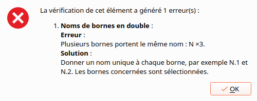
| Two or more terminals share a name | error — the save is blocked, and the terminals involved are selected so you can find them |
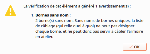
| One or more terminals have no name | warning — the save goes ahead. Sheet reports, conductor definitions and thumbnails are not checked |
How names are compared:
- Spaces at the start and end are ignored:
PEandPEare the same name. - Case counts:
nandNare different names. - Unnamed terminals are counted as unnamed, never as duplicates of each other.
Real devices sometimes print the same marking twice. Some Shelly relays
have two terminals marked N or two marked L, bridged inside the device. The marking on the device is still not enough
for the drawing: IEC 61666 §4.2 says that when the manufacturer's marking is
insufficient to tell terminals apart, you assign your own designations and
explain them. Give each one a distinct name that keeps the printed marking,
for example N.1 and N.2.
Configuration → Configurer QElectroTech → Général → Editor → Vérifier les noms des bornes à l'enregistrement (Check terminal names when saving). It is on by default. Unticked, neither the error nor the warning appears and every symbol saves as before.
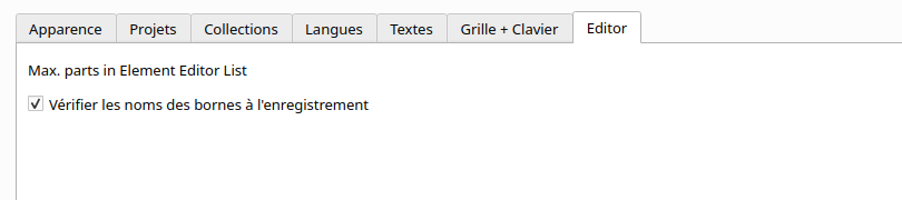
The setting belongs to your QElectroTech installation, not to the symbol or
the project. The command-line check (--check-elements, see
Automating QElectroTech) ignores it and always checks
names.
| Panel | What it gives you |
|---|---|
| Parties | every primitive in the element, as a list. Selecting in the list selects on the canvas and the other way round — the reliable way to reach a primitive buried under another one |
| Profondeur | the stacking order. A filled shape drawn last hides what is under it; this is where you push it back |
| Status bar | a live X / Y readout of the pointer, in the element's own coordinates |
The parts list gives up past 200 primitives. Above that it shows "Trop de primitives, liste non générée" with the count instead of the list, because building it for a very complex element is slow. The element is fine and still editable — only the list is withheld. The ceiling is the setting
elementeditor/max-parts-element-editor-list, so it can be raised if you routinely draw elements that big.
The canvas is an endless grid of dots, which gives nothing to judge how big a symbol will look on a real sheet. Affichage ▸ Afficher le cadre de fond (View ▸ Show background frame), also a button on the view toolbar, draws a dashed frame centred on the symbol's origin, the size of a default sheet's drawing area: 1020 × 640.
Affichage ▸ Taille du cadre de fond... (Background frame size) sets another width and height, for example the size of one cell or of the space a symbol usually gets. Both settings are remembered between sessions; the frame is off by default.
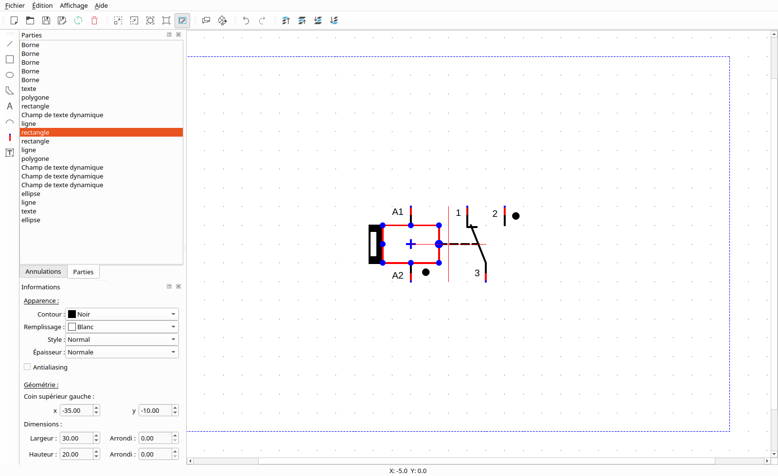
The frame is only drawn on screen. It is not saved in the symbol, and it does not appear in an SVG export.
Since PR #1164 (merged 2026-09-29).
| Action | What it does |
|---|---|
| Importer un élément à redimensionner | opens another .elmt and brings it in scaled by any X and Y factor, using the separate QET_ElementScaler program (asked for if it is not installed) — the way to build a variant of an existing symbol rather than redrawing it. To scale the element you have open and keep its terminals on the grid, see §8 |
| Importer un fichier dxf | brings DXF geometry in as primitives — see DXF import & export |
| Exporter en SVG | writes the element out as an SVG image, for documentation rather than for QElectroTech |
| Recharger l'élément | re-reads the element from disk. If you have unsaved changes it warns first, and says plainly that reloading loses them |
An element opened from a collection you cannot write to opens read-only: the title bar says so, and saving is refused. Use Save as to put a copy somewhere writable — see Managing collections for which collections are writable.
Select a primitive and drag its handles. The modifiers are the same ones the diagram editor uses, and they are worth knowing here because the element editor is where you use them most:
| Hold | While dragging |
|---|---|
| Ctrl | ignore the grid — fine positioning |
| Shift | keep proportions when resizing; snap to 15° when rotating or skewing |
| Alt on a corner | turn a rectangle or an ellipse into a polygon, so each corner moves on its own |
The full list is on Mouse modifiers.
Status: pending. This section describes PR #1378, not yet merged. Nothing here works until that lands — check the PR before trying any of this against your own build. This section will drop this notice once it does.
Édition → Mettre l'élément à l'échelle… (Edit → Scale element…) scales every part at once by ×0.5 to ×4, offering only the factors that keep the terminals on the grid. Texts, terminal names and arrows scale with it, and one undo restores the element. Which factors you get, and why, is on Grid size and element size §4.
- PLC master tables. Setting a master element's type to PLC replaces the usual contact-budget controls with an interactive I/O table — see Linking elements §5. No element in the shipped collection currently uses this.
- Line style (weight, colour, dash pattern) is set per-primitive from its own properties panel, not the toolbar.
- Grid and snap work the same way as the diagram editor.
See also: Linking elements · Elements XML · DXF import & export · Variables & formulas · Mouse modifiers · Managing collections · Grid size and element size
