Repository navigation
grid_and_element_size
Elements from different sub-collections — or different authors — can look very different in size next to each other on the same sheet, even though they all snap correctly to the same grid. New users sometimes read this the way model railway modellers read gauges: N, HO, and O scale are all "the same kind of thing" (a train) drawn at deliberately different, named miniaturization ratios. QET has no equivalent. There is no small set of named element scales, and no dialog anywhere that lets you pick one. What exists instead is one grid unit (a spacing convention, not a physical size) and a shipped collection where every author picked their own multiple of it. This page explains both halves: the grid itself, and why symbol size still varies as much as it does.
Source: sources/diagram.cpp, sources/diagram.h, sources/editor/elementscene.cpp,
sources/ui/configpage/generalconfigurationpage.cpp.
The sheet grid is a set of dots at regular intervals, purely for visual
alignment and mouse-snap — it carries no unit of measurement (not mm, not
inches). Seven settings control it, all under QSettings key prefix
diagrameditor/:
| Setting | QSettings key | Default | Controls |
|---|---|---|---|
| X grid spacing | Xgrid |
10 | horizontal dot spacing / snap step |
| Y grid spacing | Ygrid |
10 | vertical dot spacing / snap step |
| X keyboard-nudge step | key_Xgrid |
10 | how far → and ← move a selection |
| Y keyboard-nudge step | key_Ygrid |
10 | how far ↑ and ↓ move a selection |
| X fine-nudge step | key_fine_Xgrid |
1 | → / ← step while the fine-movement modifier is held |
| Y fine-nudge step | key_fine_Ygrid |
1 | ↑ / ↓ step while the fine-movement modifier is held |
| Text grid | text_grid_divisor |
1 | dragged texts snap to the grid divided by this: 1, 2, 5 or 10; 0 turns the snap off |
All seven are exposed on the General page of Configuration → Configurer QElectroTech (see Preferences reference §1, "Grid and keyboard movement"). The in-app spin boxes cap X/Y grid spacing at 1–30; there is no upper cap in the underlying setting itself, only in that dialog.
Two more settings — grid_pointsize_min and grid_pointsize_max, both
defaulting to 1 — control how thick the grid dots are drawn, ramped between
the two values as you zoom in from 100% up to 500% (Diagram::drawGrid()).
This is purely cosmetic: it does not change spacing or snap behaviour, only
how visible the dots are at a given zoom level.
Mouse-drag movement snaps to Xgrid/Ygrid, independent of the
keyboard-nudge settings above; Ctrl while dragging bypasses the snap. Texts
are the exception: they snap to the text grid, the sheet grid divided by
text_grid_divisor, so a label can sit between two grid points and still
line up with the labels of other symbols. The default of 1 is the sheet grid
itself. See Mouse modifiers §2 for where to change it
and for the full modifier table.
The element editor (Edit element / drawing your own symbol — see
Using the element editor) works on its own 1×1 fine
grid by default (ElementScene::setGrid(1, 1)), letting you place a line
or terminal at any integer coordinate while you draw. That fine positioning
does not carry over to the saved element, though:
On save, ElementScene rounds the element's bounding box up to the next
multiple of 10 in both width and height (with an extra +10 if the
remainder already exceeds 6, so it rounds to the nearer multiple of 10,
not always up):
int upwidth = ((qRound(size.width())/10)*10)+10;
if ((qRound(size.width())%10) > 6)
    upwidth += 10;
and the same for height. The padding needed to reach that size is split out
as a margin, and the whole element is written to .elmt with width and
height attributes that are always multiples of 10 — the same 10 that is
the diagram grid's default spacing. An element's hotspot always lands on a
grid intersection once it's placed on a sheet. The rounding does not reach
the terminals, though: a terminal is only on a grid point if it was drawn a
whole number of grid steps from the hotspot. In the shipped collection
(checked 2026-10-08), 3,287 of the 6,080 elements that have terminals have
all of them on the 10-unit grid; the other 2,793 have at least one
terminal between grid points, so a wire drawn straight to it from a
neighbouring element bends.
If you've changed Xgrid/Ygrid away from 10, note that the element
editor's own rounding is still hard-coded to 10 — an element built on a
sheet with a 12-unit grid, say, will not necessarily land back on that
grid's intersections.
Rounding to a multiple of 10 says nothing about which multiple. A survey
of the shipped elements/ collection (8,838 .elmt files) shows every
<definition> width/height is indeed a multiple of 10 — but the multiple
chosen ranges enormously:
| Element | File | Size (grid units) |
|---|---|---|
| Mechanical lock (auxiliary symbol) | 10_electric/98_graphics/01_auxiliary_symbols/verrouillage-meca.elmt |
20 × 20 |
| WAGO 750-1606 I/O module | 10_electric/20_manufacturers_articles/wago/.../wago_0750-1606-0040-0000.elmt |
740 × 110 |
That's a 35× difference in linear footprint between two ordinary elements,
both perfectly grid-aligned. It isn't an outlier: dimension pairs like
30×30, 40×20, 60×60, and 140×310 are all common across the
collection in the hundreds, because each contributor drew their symbol at
whatever size looked right to them, at whatever level of physical detail
they were rendering (a single auxiliary-contact glyph vs. a full
manufacturer footprint traced from a datasheet). There's no schema field,
naming convention, or qet-lint rule (checked in tools/qet-lint/) that
enforces or even flags a consistent size within a symbol family — the
mechanical-lock-sized problem is a purely visual one you only notice once
two mismatched elements sit on the same sheet.
Practical takeaway: don't expect elements from different sub-collections
— or the same sub-collection at different manufacturer generations — to
read at a consistent visual scale just because they're both grid-aligned.
If a diagram's symbols look inconsistently sized after adding a new part
from a different collection, that's expected behavior, not a bug: check the
element's width/height in its .elmt file (or via Edit element)
against neighbouring symbols. To make one bigger or smaller without taking
its terminals off the grid, see §4.
Status: pending. This section describes PR #1378, not yet merged. Nothing here works until that lands — check the PR before trying any of this against your own build. This section will drop this notice once it does.
In the element editor, Édition → Mettre l'élément à l'échelle… (Edit → Scale element…, the last item of the menu) scales the whole element by one factor. It only offers the factors that keep every terminal on the 10-unit grid, so wires to the scaled element stay straight.
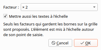
How the factors are chosen. The candidates are ×0.5, ×1.5, ×2, ×2.5, ×3 and ×4. The element is scaled about its hotspot, so a terminal at (x, y) moves to (x × factor, y × factor). A factor is offered only if that lands every terminal on a multiple of 10. In practice:
| Terminals today | Factors offered |
|---|---|
| all a multiple of 20 from the hotspot | all six |
| all a multiple of 10, some not of 20 | ×2, ×3, ×4 |
| some 5 units off the grid | ×2, ×4 — these bring them on to the grid |
| some off by another amount (1, 2, 7 …) | none: the dialog says so and OK is greyed out |
| no terminals at all (a front view, a logo) | all six |
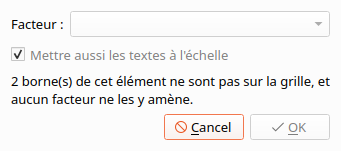
For the shipped collection, ×2 and ×3 are always offered for an element whose terminals are on the grid. ×0.5 and ×1.5 are offered for about a quarter of them. Making elements smaller is usually not possible this way.
The grid is fixed at 10 here, whatever Xgrid/Ygrid are set to in your preferences: elements are shared between users, and the collection is drawn to 10.
What scales:
| Part | What happens |
|---|---|
| lines, rectangles, circles, ellipses, arcs, polygons | size and position × factor, the same as dragging the selection handles |
| arrows and other line ends | their length × factor |
| terminals | position × factor; a terminal's displayed name moves out with it (its offset × factor, its font as for texts) |
| texts and dynamic text fields | position × factor; with Mettre aussi les textes à l'échelle (scale texts too, ticked by default) the font size too, rounded to a whole point and never below 4 pt |
| line thickness | unchanged — thickness is chosen from a short list of styles, not set as a size |
Undo. The whole change is one step in the undo list (mise à l'échelle de l'élément); one Ctrl+Z puts every part back.
Projects that already use the element. A project keeps its own copy of each element, so nothing changes in a project until you update the element there. Terminals keep their uuid when scaled. After updating, check the wires to that element, since its terminals are now somewhere else.
Compared with Importer un élément à redimensionner. The element
editor's Fichier menu already has Importer un élément à redimensionner
(import an element to resize). That runs plc-user's separate
QET_ElementScaler program,
which you install first. It takes any X and Y factor, with no grid check,
and brings in another .elmt file. Use it for free or uneven scaling. Use
Mettre l'élément à l'échelle… to scale the element you have open while
keeping its wires straight.
- Preferences reference — where the grid settings live in the UI
- Using the element editor — drawing tools, saving, checks
- Mouse modifiers — Shift/Ctrl/Alt while dragging
- Aligning items — putting symbols that left the grid back on it
-
Elements XML — the
<definition>width/height/hotspotattributes
