Repository navigation
terminal_strips
A terminal strip in QElectroTech is a separate object from the terminals drawn on your sheets. The sheet terminals stay where they are; the strip is a list that references them, adds the terminals that exist only in the cabinet, records levels and bridges, and can be drawn on a sheet as a strip plan.
Status: marked (DEV). The menu entry is Project → Terminal strip manager (DEV), and that label is in the shipped source. The feature works and its data is saved in the project file, but the developers have not declared it finished. Treat it as usable and evolving rather than settled.
Source: sources/TerminalStrip/ — terminalstrip.cpp, physicalterminal.cpp,
realterminal.cpp, terminalstripbridge.cpp, and ui/ for the editor.
The model has three layers, and almost every confusion about terminal strips comes from collapsing two of them.
| Object | Is | Example |
|---|---|---|
| Terminal strip | the whole strip |
-X1, 24 terminals on a rail |
| Physical terminal | one block clipped onto the rail | position 7 on -X1
|
| Real terminal | one electrical level within that block | the front level of position 7 |
A physical terminal is composed of one or more real terminals. One real terminal is an ordinary single-level block. More than one means the block has levels — a two- or three-tier terminal.
Levels are ordered back to front, from the mounting plate towards the cabinet door:
mounting plate                                   door
      |                                            |
      |   +---+                                    |
      |   | 0 |  +---+                             |
      |   |   |  | 1 |  +---+                      |
      |   |   |  |   |  | 2 |                      |
      |   +---+  +---+  +---+                      |
      |                                            |
      |<---- one physical terminal, 3 levels ----->|
Level 0 is the back. That ordering is the same one the editor's Level column shows and the same one bridging compares against.
A real terminal does not have to correspond to a drawn terminal element. A terminal you have reserved on the rail but not drawn — a spare, a future connection, a manufacturer-supplied end block — exists in the strip as a real terminal with no element behind it.
This is why a strip's terminal count can legitimately exceed the number of terminal elements in your sheets.
Do not confuse these with the editor's Independent terminals list, which is the opposite case: terminals drawn on a sheet that are not in any strip yet. Moving those into a strip is covered in §2, Moving drawn terminals into a strip.
Project → Terminal strip manager (DEV) opens the editor window. It shows the project's strips in a tree on the left, and the selected strip's terminals in a table.
A strip carries five pieces of identification: installation, location,
name, comment and description. Installation and location are the
same concepts as a sheet's plant and locmach — a strip is addressed the same
way an element is.
Terminals reach a strip by being added to it, either from the drawn terminal elements the project already has, or as free terminals you create in the strip itself. The first case is described below.
| Column | Meaning |
|---|---|
| Position | order on the rail |
| Level | which tier of a multi-level block, 0 = back |
| Label | the terminal's number or name |
| Conductor number | the wire number arriving |
| Cross-reference | where the terminal is drawn |
| Cable | cable this terminal belongs to |
| Cable wire colour / number | the core within that cable |
| Type | generic, fuse, sectional, diode, ground |
| Function | generic, phase, neutral |
| LED | whether the block carries an indicator |
Type and function come from the terminal element's own definition — see Linking elements for how an element declares them.
Drag and drop, and the tooltips that say why the button is greyed out, are in the nightly builds from 1 October 2026 onwards (#1198, #1199). Release 0.100 has the button only.
Every terminal element drawn on a sheet that is not yet in a strip is listed in the tree under Independent terminals. Click any one of them and the right-hand side shows all of them in a table, with the move controls at the top right.
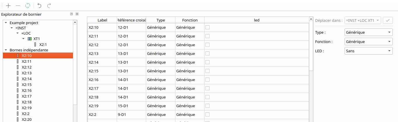
Selecting a terminal in the tree does not select it in the table. The tree item you click only opens this page. Both ways of moving work on what is selected in the table (or, for a drag, on what you drag). In the picture above, X2:10 is selected in the tree but no row of the table is, so the button is greyed out.
There are two ways to move terminals into a strip.
1. The button. Select one or more rows in the table (Ctrl+click or Shift+click for several), choose the strip in Move to, and click the ✓ button next to it.
2. Drag and drop. Drag the terminals onto a strip in the tree on the left:
| Drag from | What moves |
|---|---|
| the table | every selected row |
| the tree, under Independent terminals | the terminal you drag, one at a time |
Drop them on the strip itself, or on any terminal already in that strip. They are added after the strip's existing terminals, and the strip is then selected, so you see the result straight away:
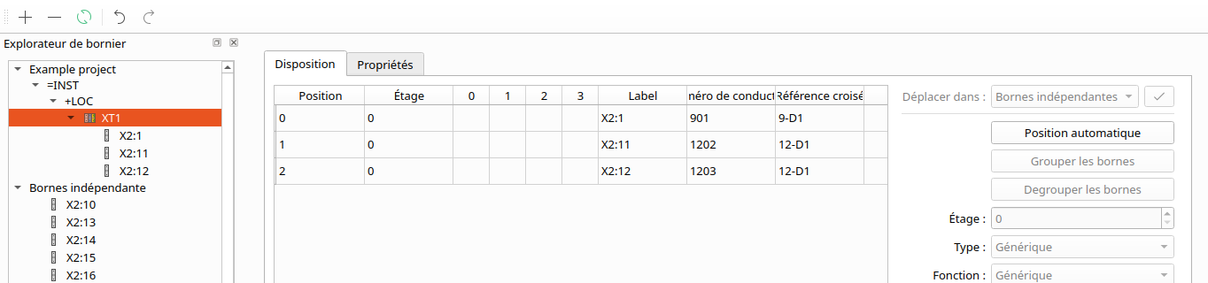
Either way, the move is one undo step: the undo button in the manager's toolbar puts every terminal of that move back.
Hover over it: the tooltip says why. When more than one reason applies, it names the most basic one first.
| Situation | Tooltip | What to do |
|---|---|---|
| The project has no strip yet | The project has no terminal strip: create one with the + button | create a strip with the + button at the top left of the manager |
| You changed cells in the table (shown in yellow) and have not applied them | Apply or cancel the current changes before moving | click Apply or Reset at the bottom first |
| No row of the table is selected | Select the terminals to move in the table | select the rows to move |
A drop is refused, and nothing moves, in the same pending-changes case, and whenever it is not over a strip or one of its terminals. Moving reloads the table, which would throw away changes not yet applied; that is why both the button and the drop wait for Apply or Reset.
- taking terminals back out of a strip, or moving them from one strip to another — the strip's own page has a Move to list for that, which includes Independent terminals;
- changing the order of terminals within a strip.
Two operations change the shape of the strip rather than its contents:
- Grouping takes several real terminals and makes them levels of one physical terminal. That is how you tell QET "these three are one three-tier block", not three blocks.
- Ungrouping reverses it, giving each real terminal a block of its own.
Sorting sets the order of physical terminals on the rail. Both are undoable — the module has its own undo commands for grouping, sorting, level changes, bridging and colour.
A bridge (comb, jumper) links terminals that must be at the same potential. QET's rules are strict, and knowing them saves guessing why the bridge button is greyed out. To be bridgeable, the selected real terminals must:
- number at least two;
- all belong to this strip;
- all be at the same level — you cannot bridge a front level to a back one;
- be consecutive on the rail;
- belong to different physical terminals — the levels of one block are not bridged to each other;
- include at least one terminal that is not already bridged.
Fail any of the six and the operation is refused rather than partially applied.
Bridges carry a colour, chosen from a fixed palette — red, blue, white, dark grey, black — with dark grey the default. The colour is a drawing convention, not electrical meaning; use it consistently across a project and it reads as documentation.
A strip can be placed on a sheet as a graphical item. What gets drawn is governed by a layout pattern, a named, reusable set of geometry: header rectangle and text orientation, spacer, per-level terminal rectangles, terminal and cross-reference text height, position and orientation, font, and the diameter and vertical offsets of the bridge dots.
Layouts are managed per project, so a house style can be defined once and applied to every strip.
The drawing supports up to four levels. The layout pattern holds four terminal rectangles and four bridge-point offsets. The data model itself does not impose that limit — a physical terminal can hold more real terminals than the drawing has rows for. If you build five-level blocks, the model will keep them; the strip plan will not show them all.
Strips live in the project file, not in the sheets:
<project>
    ...
    <terminal_strips>
        <terminal_strip>
            <terminal_strip_data uuid="{…}">
                <informations>
                    <information name="installation">…</information>
                    <information name="location">…</information>
                    <information name="name">-X1</information>
                    <information name="comment">…</information>
                    <information name="description">…</information>
                </informations>
            </terminal_strip_data>
            <layout>
                <!-- one entry per physical terminal, each listing its
                     real terminals in level order -->
            </layout>
            <terminal_strip_bridge>…</terminal_strip_bridge>
        </terminal_strip>
    </terminal_strips>
</project>
Empty identification fields are omitted rather than written blank, so a minimal strip's XML is short.
Real terminals are stored by the uuid of the element they refer to. On load, the strip is reconnected to the project's terminal elements by that uuid; real terminals with no element are rebuilt as free terminals. This is the usual consequence of identity being element-based: an element that loses or changes its uuid loses its place in the strip.
- The feature is labelled (DEV) in the interface. Its data is saved and reloaded, but its scope is still moving.
- The strip is a view over your terminals plus the ones only it knows about. It does not renumber your sheets and does not create terminal elements.
- Terminal renumbering is a separate feature — see
auto_num_lockedin Linking elements for how to exempt a terminal from it. - Nothing in the shipped example projects uses terminal strips, so there is no worked example in the box to copy from.
See also: Conductors — the wire properties, and the Cable field · Linking elements · Variables & formulas · The project database
