Repository navigation
conductors
A conductor is the line joining two element terminals. It is the object you place most and configure least, and its properties dialog carries about twenty fields — several of which exist only to fill a column in an export, and two of which currently do nothing at all.
This page is the reference for those fields: what each one does, where it is stored, and which export reads it. For a walkthrough of drawing wires, see User manual → Drawing Wires & Conductors.
Every conductor is one of two types, and the choice changes which half of the properties dialog applies.
| Type | Shows | Used for |
|---|---|---|
| Multi-wire (default) | a line with a text label | ordinary multi-line schematics, one conductor per wire |
| Single-line | a line with symbols — phase ticks, earth, neutral — and no text | single-line (one-line) diagrams, where one line stands for a whole circuit |
Switching type does not lose the other type's settings: both are stored, and only the relevant half is drawn.
There are three levels, and they are separate places in the interface. A new conductor takes the sheet default; changing that default does not rewrite conductors already drawn.
| Level | Where | Applies to |
|---|---|---|
| Application default | Preferences → New project | conductors in projects you create from now on |
| Sheet default | the sheet's properties dialog | conductors drawn on that sheet from now on |
| One conductor | double-click the conductor, or the Selection properties panel (below) | that conductor only |
To change many existing conductors at once, select them and use Search & Replace, which edits conductor properties in bulk.
The Selection properties panel, on the right of the editor, can show the selected wire's properties, so you can change them without opening the dialog. It is off by default. Turn it on in Settings → Configure QElectroTech → General → Appearance with Show the properties of a selected conductor in the Selection properties panel.
With it on, select a wire, or click its number, and the panel shows the same fields as the dialog.
- A change applies when you leave the field, press Enter or tick a box. Each change is one undo step.
- Apply properties to all conductors of this potential (Apply properties to all conductors of this potential), above the fields, sends each change to every wire of the same potential, as the dialog's box of the same name does. The panel remembers this box between sessions, unlike the dialog.
- If the wire is changed elsewhere (the dialog, undo, the colour button), the panel updates to match.
Fixed on 1 October 2026 by PR #1204. In builds made before that, pressing Enter in a text field of the panel (Function, Section...) could also untick the Multiline box around it: the wire became single-line and gained phase, neutral and earth symbols. Any edit in the panel could also change a dash size of 1 to 2.
On such a build, leave a field with Tab or by clicking elsewhere rather than Enter, and check the wire type after editing; Ctrl+Z undoes the change. Builds with the fix change only the fields you edit, and Enter just applies the field.
Select several wires, by clicking with Ctrl or by drawing a box across them. A box that also catches the wire numbers is fine: a selected number counts as its wire. A line above the fields says how many wires are selected.
Only the fields you change are applied, to every selected wire. Setting the function on ten wires gives all ten that function, and each keeps its own number, cable, section and the rest.
What the fields show:
- A text field the wires do not agree on (Function, Section, Cable,
Tension / protocol...) is blank, with the hint Several values
(Several values). Type a value and every selected wire takes it, even if
some already had it: on a 1.5 mm² wire and a 2.5 mm² wire, typing
1.5in Section gives both 1.5 mm². - A text field they all agree on shows that value.
- Every other field (colours, sizes, checkboxes, alignment) shows the value of the first wire: the one highest on the sheet, and of those the leftmost.
- Text (the wire number) is locked while several wires are selected, since the same number on all of them would make duplicates. To give a whole potential one number, select one of its wires and tick Apply to all conductors of this potential.
| You do | Every selected wire | Untouched |
|---|---|---|
set Function to 24V DC
|
gets function 24V DC
|
its own number, cable, section, colour... |
set Section to 2.5, then Function to PWR
|
gets both, as two undo steps | everything else |
| tick Apply to all conductors of this potential, then edit | every wire of every selected wire's potential gets the edited field | each wire's other fields |
Each edit is one undo step for all the wires.
Limits:
- Fields other than text fields are not marked when the wires differ. To give every wire the first wire's colour or size, change it to something else and back, or use the dialog on each wire.
- A blank "Plusieurs valeurs" field cannot be used to empty the field on every wire: leaving it blank changes nothing.
- Selecting wires together with symbols or texts leaves the panel empty, as it does for any mixed selection.
Stored in the .qet file on each <conductor> element, under the attribute
named in the last column.
| Field | What it is | XML attribute |
|---|---|---|
| Text / number | the wire number shown on the diagram | num |
| Formula | the expression the number is derived from, for auto-numbering | formula |
| Function | free text: what the wire is for | function |
| Voltage / Protocol | free text: voltage or bus protocol, e.g. 24VDC, Profibus
|
tension_protocol |
| Wire colour | free text naming the physical wire colour, e.g. BN, bleu — not the colour it is drawn in |
conductor_color |
| Wire section | free text: cross-section, e.g. 1.5mm²
|
conductor_section |
| Cable | free text | cable |
| Bus | free text | bus |
Cable and Bus are stored but unused. They are saved to the project, come back on reload, and appear in the dialog — but nothing reads them: no export, no report, no drawing. Fill them in if you want the data recorded for later; do not expect them to show up anywhere yet.
| Field | What it does | XML attribute |
|---|---|---|
| Colour | the colour the line is drawn in | color |
| Two-colour | draws the line in two alternating colours |
bicolor, color2
|
| Dash size | length of each colour segment when two-colour is on | dash-size |
| Style | solid, dashed, dotted, dash-dotted | style |
| Thickness | line width | condsize |
| Field | What it does | XML attribute |
|---|---|---|
| Show text | draw the number, or hide it | displaytext |
| One text per sheet | show the number once per potential per sheet, on the longest conductor of that potential, and hide it on the rest | onetextperfolio |
| Size | text size, default 9 | numsize |
| Text colour | — | text_color |
| Rotation | angle for the label on horizontal and on vertical runs, default 0° and 270° |
horizrotatetext, vertirotatetext
|
| Alignment | where the label sits relative to the line |
horizontal-alignment, vertical-alignment
|
Conductors joined through elements form a potential — an equipotential net. "One text per sheet" is what stops the same wire number being repeated a dozen times along one potential.
The setting that counts is the sheet's own, in the sheet's properties (Activate the option text by potential). Since PR #1191 (merged 2026-10-01) the drawing follows it as soon as you press OK: unticking shows the hidden wire texts, ticking hides the repeats. Before, nothing changed until each wire was edited or the project reopened, which made the option look broken (bugtracker #344). The project's own setting, under the project properties' Conductors tab, still only applies to sheets created afterwards.
Only drawn when the type is single-line:
| Field | What it draws | XML attribute |
|---|---|---|
| Phases | that many phase ticks across the line | phase |
| Neutral | the neutral symbol | neutral |
| Earth | the earth symbol | ground |
| Protective conductor (pen) | the PEN symbol | pen |
This is the practical answer to "why is this field here". Blank fields become blank columns.
--export-cables — the from-to wiring list, one row per conductor. The
menu entry Project → Export the wiring diagram writes the same CSV file.
| Column | Comes from |
|---|---|
| Page | the sheet the conductor is on, as its number is shown on the sheet |
| Component 1 / Terminal 1 | the element and terminal at one end |
| Component 2 / Terminal 2 | the element and terminal at the other end |
| Tension / Protocol | Voltage / Protocol |
| Wire colour | Wire colour (the text field, not the drawn colour) |
| Wire section | Wire section |
| Function | Function |
| Cable | cable — last column, in the nightly builds from 1 October 2026 onwards (#1197); release 0.100 does not have it |
A wire drawn through a sheet report (an arrow to another sheet) is one row, not two. Its fields are taken from both halves: written once when the halves agree, both values separated by a comma when they do not. That is when each report of the linked pair has exactly one wire. With several wires on a side, the drawing does not say which is wired to which, so each wire gets its own row ending at the report (#1184).
--export-wires produces the conductor-number list.
--export-wiring produces a from-to list too, but from the project
database rather than the document — and the database's conductor table
stores only the two terminals and the wire number. None of the documentation
fields above exist in it, so this export cannot carry tension, wire colour,
section or function. If you want those columns, use --export-cables.
See CLI reference for the commands, and Building a nomenclature query for the BOM/summary builder.
Project → Wiring list (database) shows the same from-to list in a window, one row per conductor:
| Column | |
|---|---|
| Wire | the wire number |
| Component 1 / Terminal 1 | the element and terminal at one end |
| Component 2 / Terminal 2 | the element and terminal at the other end |
| Sheet | where the conductor is |
Rows are ordered by sheet, then by wire number — numeric wire numbers first in
numeric order, so 9 comes before 10, then anything non-numeric as text.
Two things this window tells you that the CSV does not:
- It refreshes the database before querying, so a wire number you changed earlier in the session is already in the list.
- It counts what it left out. A conductor whose end is not attached to any element cannot appear in a from-to list, and the window says how many were excluded rather than presenting a short list as if it were complete. If that number is not zero, something on a sheet is not connected to what you think.
Being database-backed, it carries the same limitation as --export-wiring: no
tension, wire colour, section or function columns, because the database does
not store them.
QElectroTech has no cable object. There is no cable in the data model, no cable table in the project database, and no way to group several conductors into one cable and give it a designation, a type or a core count.
What exists is smaller than the name suggests:
| Thing | What it really is |
|---|---|
| The cable field on a conductor | free text, stored and reloaded; written as the last column of the wiring list export (nightly builds from 1 October 2026), and readable from a script |
The --export-cables command |
the from-to wiring list — one row per conductor, not per cable |
So a conductor can record which cable you intend it to belong to, and that text survives in the file, but nothing inside QElectroTech collects conductors into cables, checks core counts, or draws a cable list. Search & Replace does not cover the field either, so renaming a cable means editing each of its wires.
Until QElectroTech has a cable list of its own, the wiring list export gets you most of the way:
-
Give each wire its cable name. Double-click the wire to open its properties and type the name in the cable field, for example
W1. The name is saved with the project. -
Export the wiring list: Project → Export the wiring diagram (Export the wiring diagram), or on the command line:
qelectrotech --export-cables project.qet wiring.csv
-
Open the CSV in a spreadsheet (the separator is a semicolon) and sort or filter on the last column, Cable. Each cable's wires are then together, with both ends of each wire, its colour and its section. Counting the rows per cable gives the number of cores used.
Wires with no cable name have an empty last column; filter them out, or sort them to the end.
Discussion #956 is about a real cable model inside QElectroTech; the export above is what works today.
A conductor routes itself between its two terminals. Drag any segment to shape it by hand, and that shape is saved with the project.
Ctrl+K — "Reset conductors" discards hand-routing on the selected conductors and recalculates their paths automatically. It is the way out of a tangle, and it is not undoable by re-dragging — the original shape is gone.
Hand-routed shapes are stored as explicit segments. If a stored shape no longer matches where its terminals are — because something moved without the path being updated — QElectroTech quietly discards it on load and re-routes automatically. The drawing looks fine; the hand-routing is lost.
The same happens when a stored segment length is not a usable number — a
project file damaged by an outside tool or a disk error, with nan or inf
where a length should be. The conductor is routed automatically on load and
the file saves normally from then on. The storage format is described in
conductors (XML).
The Conductor color swatch on the Diagram toolbar colours every selected conductor in one click:
- Select the conductors: one, several, or Ctrl+A for the whole sheet.
- Open the swatch and pick a colour.
The menu lists the colours electricians name — Noir, Marron, Gris, Bleu, Vert, Rouge, Orange, Violet, Blanc (black, brown, grey, blue, green, red, orange, violet, white) — then the custom colours you picked this session under Recently used, then Other color… for the full colour dialog.
What it does:
- Whole wires, not segments. A wire split into several segments by junctions is recoloured along its whole electrical potential, as the properties dialog does.
- One undo step for the whole selection.
- The next wire too. The picked colour becomes the colour of the next conductor you draw. With nothing selected, picking a colour only does that.
- Nothing is saved as a setting. The colour lives on the conductors it was applied to; the recent list is forgotten when QET closes.
The swatch is greyed out when no sheet is open or the project is read-only.
F2 still opens the colour picker for exactly one selected conductor, and does nothing with several selected or none.
Double-click a colour to apply it. In the colour dialog opened by F2 or by Other color…, a double-click on a colour picks it and closes the dialog, as OK does; a single click still only selects it (PR #1172, merged 2026-09-30). This works where QElectroTech uses Qt's own colour dialog — always on Windows. Where the desktop's own dialog is shown instead (macOS, and Linux desktops such as GNOME or KDE), nothing changes.
For bulk changes across sheets by some other criterion, use Search & Replace.
There are no named conductor presets. A project has a single default set of conductor properties, not a library of named ones; the request for that is issue #461. Older documentation referring to a "project conductor list" describes something that does not exist.
| Setting | Where | What it does |
|---|---|---|
| Automatic creation conductor (s) | Project menu / toolbar | when you place an element whose terminals land on existing ones, wires them up for you |
| Automatic disconnection of conductor(s) | Project menu / toolbar | placing an element on an existing conductor splits it and connects both halves |
Both are per project, and both are toggles you can leave off.
Where two wires cross without being connected, a project can draw a small arc — a hop — on one of them, so the crossing cannot be read as a connection. Until now the only way to show this was to insert a jump symbol and split the wire around it (#436).
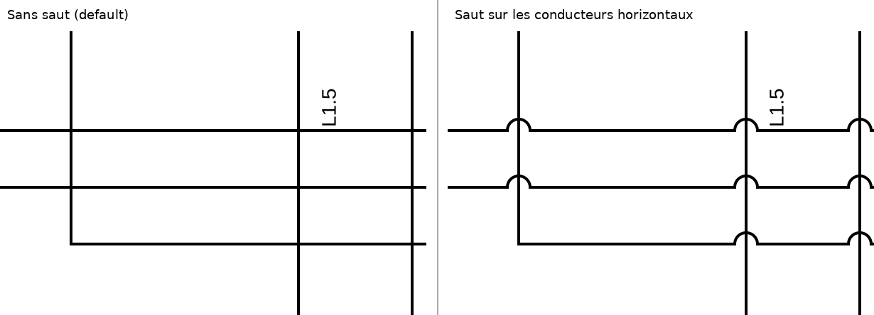
It is off by default. Many drawing conventions, the French one among them, do not use hops; a project that never turns them on is drawn and saved exactly as before.
Project → Project properties, page General, the Conductor crossings list at the bottom:

| Choice | What is drawn |
|---|---|
| No hop — the default | crossings as plain lines |
| Hop on horizontal conductors | the horizontal wire arcs over the vertical one |
| Hop on vertical conductors | the vertical wire arcs to the right of the horizontal one |
You choose the orientation rather than "whichever wire was drawn last", so
the whole project looks consistent. The setting belongs to the project: it
is saved in the .qet file and every sheet follows it, on any computer.
- Only a real crossing hops: one wire passing straight through another.
- A wire that ends on another one (a T, usually with a junction dot), or turns on it, is a connection, not a crossing, and never hops.
- A crossing too close to a bend or to the end of a wire for the arc to fit is drawn as a plain crossing.
- Of two crossings closer together than one arc, only the first hops.
- Drawing only. No element is added and no wire is split: the wire numbers, the wiring list, the parts list and the project database are exactly the same with or without hops.
- Exports: PDF, SVG, image export and printing all show the hops. DXF export does not — it writes the wire segments itself and draws crossings as plain lines.
-
In the file: a project with hops on carries
<wire_crossings hop="horizontal"/>(or"vertical"). Without that element, or with any other value, no hop is drawn — so an older version of QElectroTech simply shows plain crossings.
- User manual — the walkthrough for drawing wires
- Wires per terminal — an optional limit on wires per terminal (PR #1272)
- Auto-numbering — how wire numbers are generated and frozen
- Linking wires across pages — sheet reports
- Terminal strips — where conductors land on real terminals
- Search & Replace — changing many conductors at once
- Showing and hiding kinds of items — hiding every wire number for a while (Display ▸ Display ▸ Conductor texts)
- CLI reference — the export commands above
- Mouse modifiers — Ctrl while dragging, and the rest
