Repository navigation
generic_devices
Status: pending. Everything on this page describes PR #1418, not yet merged. Nothing here works until that lands — check the PR before trying any of this against your own build. This page will drop this notice once it does.
Some devices appear in a project once and never again: a particular drive, a power supply, a controller, a sensor with eight wires. Drawing a proper symbol for each one in the element editor takes longer than the rest of the sheet. A generic device is the quick answer: a plain rectangle with named terminals on whichever sides you want, sized to fit, made by a short wizard and put straight on the cursor.
The result is an ordinary symbol, not a special kind of item. It is written into the project's own collection like any imported element, so everything that works on symbols works on it: wires, labels and auto-numbering, the parts list, terminal strips, every export. A project holding one opens in any version of QElectroTech.
Grew out of issue #410; proposed in discussion #1233.
Any of these, with a project open and editable:
| Route | |
|---|---|
| Menu | Edit → Add → Add a generic device… |
| Toolbar | the box-with-terminals button at the end of the Add toolbar |
| Command search |
Ctrl+Shift+M, type generic device, Enter |
It has no keyboard shortcut by default. Like every command, it can be given one, or moved to another toolbar, in the Customize dialog (see Customising QElectroTech). If you customised the Add toolbar before this button existed, your own list is kept and the button is not added to it: put it there from Customize.
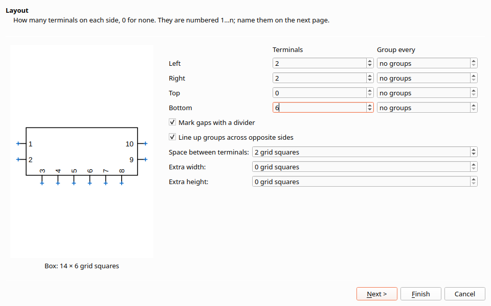
The wizard has three pages. A preview of the box sits beside every page and redraws as you type, with its size in grid squares and any warnings underneath. Finish is available from the first page: a box with numbered pins needs nothing more.
| Setting | What it does |
|---|---|
| Terminals (per side) | How many terminals on the left, right, top and bottom. 0 for none. New terminals are named by pin number (below). |
| Group every (per side) | Leave a gap after every N terminals: 9 terminals grouped by 4 gives 4, gap, 4, gap, 1. "no groups" turns it off. |
| Mark gaps with a divider | Draws a short line on the inside of the box edge at each gap, so power, control and earth read as separate blocks. On by default. |
| Line up groups across opposite sides | When facing groups have different lengths, adds blank rows to the shorter one so the gaps meet. On by default. |
| Space between terminals | 1 to 5 grid squares; 2 by default. At 1 the names of neighbouring terminals overlap, and the preview says so. |
| Extra width / Extra height | Grid squares added to the automatic size. The box can be made bigger than it needs, never smaller. |
Pin numbers. Terminals created here are numbered counter-clockwise from the top of the left side, as on an IC package: down the left side, along the bottom from left to right, up the right side, then along the top from right to left. Gaps take no number. While the names are still the automatic ones, changing a count renumbers everything; once you have typed a name, only new terminals get numbers.
Line-up, by example. Left L1 L2 L3 N | PE, right U V W | PE. Without
line-up the two PEs land on different rows. With it, the right-hand group
gets one blank row, so PE faces PE and a wire between them is straight.
Going back. Back from page 2 shows the counts as they now are. Changing a count adds or removes terminals at the end of that side and keeps every name already typed. Changing Group every re-lays that side's gaps; if you made gaps by hand on page 2, the wizard asks before replacing them.
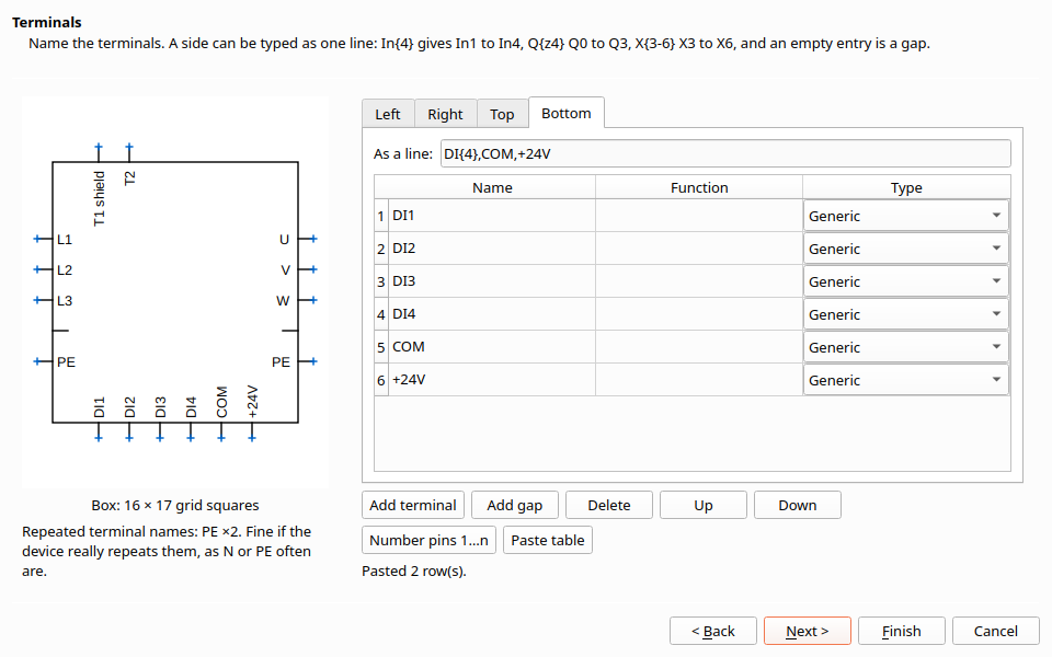
One tab per side. Each has a table — Name, Function, Type — and above it the same list written as one line (As a line). Edit either; the other follows.
Writing a side as one line. Entries are separated by commas:
| You type | You get |
|---|---|
L1,L2,L3 |
L1, L2, L3 |
L3,,PE |
L3, a gap, PE (an empty entry is a gap) |
In{5} |
In1 … In5 |
Q{z5} |
Q0 … Q4 (z counts from zero) |
X{3-8} |
X3 … X8 |
X1:{4} |
X1:1 … X1:4 (the number can sit anywhere in the name) |
{2}.1 |
1.1, 2.1 |
One {…} per entry, at most 200 terminals from one entry. A line that cannot
be read shows the reason underneath and leaves the table as it was. Changing
names through the line keeps the functions and types already in the table.
A name containing a comma or a brace cannot be written in a line; that side's
line then becomes read-only and the table is the way to edit it.
The {n} and {zn} forms are those of the older
qet_gen_element side project.
The columns.
| Column | |
|---|---|
| Name | The terminal's name, drawn inside the box next to it and stored on the terminal. |
| Function | Optional. Drawn after the name: 4 with function OUT1 shows "4 OUT1". |
| Type | Generic, Inner or Outer, as in the element editor. |
Buttons.
| Button | |
|---|---|
| Add terminal / Add gap | Insert below the selected row, or at the end. |
| Delete, Up, Down | On the selected rows of the current tab. |
| Number pins 1…n | Rename every terminal by pin number (see page 1). |
| Paste table | Read the clipboard as rows of side, name, function, type (below). |
Pasting from a spreadsheet or a datasheet. Copy rows from a spreadsheet (columns separated by tabs) or a CSV file (commas):
side,name,function
left,L1
left,L2
left,L3
left,
left,PE
right,U,motor
bottom,DI1,,Inner
-
side is
left,right,toporbottom, orL,R,T,B, in any case. A first row whose side issideis a header and skipped. - An empty name is a gap. function and type are optional.
- Only the sides named in the paste are replaced; the others stay.
- Rows that cannot be read are listed under the buttons and skipped.
Repeated names get a warning icon on their row and a line under the preview. They are not refused: real devices repeat N, PE and T1.

| Field | Where it ends up |
|---|---|
| Name | How the symbol is listed in the project's collection. "Generic device" if left empty. |
| Label | The element's label, e.g. -U1, drawn in the middle of the box. |
| Manufacturer, Manufacturer reference, Description | The element information, so they reach the parts list and the project database. |
| Show the manufacturer reference in the box | Draws the reference under the label. On by default: a box with nothing in it is hard to identify. |
Everything on this page can be changed later on the placed device, in its properties, like any other element.
- Writes the symbol into the project's collection, folder Generic devices (shown under Imported elements in the Collections panel). The file name is the device name plus a short code, so two devices with the same name never overwrite each other.
- Puts it on the cursor, as when you place any element: click to drop it, Space to rotate, Escape to stop.
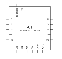
- Every terminal is one grid step outside the box, joined by a short line, and every terminal lands on a grid point. Wires to it run straight.
- Opposite sides are filled from the top (or left) at the same spacing, never spread to match, so rows line up and stay on the grid.
- The box is as small as the terminals and their names allow. The first and last terminal on a side keep clear of the names on the neighbouring side, so "+24V" at the end of the bottom row does not run into "PE" at the foot of the right side.
- Names on the top and bottom are rotated to read upward.
- Names are measured with the folio's own font, so they fit as drawn.
- Extra width / height only adds.
The worked example from the proposal — left L1,L2,L3,,PE, right
U,V,W,,PE, bottom DI{4},COM,+24V — comes out 16 × 14 grid squares.
- A placed device cannot be edited through the wizard yet. To change one, make a new device and replace it. Editing a placed device so it regrows and keeps its wires is planned as a later PR.
- No presets yet, and no "copy to my collection" button: the device lives in this project's collection only.
- Sizes are in grid squares, not millimetres. See Grid size and element size.
- The symbol can be opened in the element editor like any other. After that it is simply a symbol you drew.
See also: Using the element editor · Grid size and element size · Customising QElectroTech · Managing collections · Drawing faster
