Creating a FlyingF4 from scratch
- Buy an STM32F4Discovery
- Buy a shield with MPU6050, HMC5883, MS5611: GY-86 is a good candidate
- Wiring
- Flash the bootloader
- Flash the firmware
You now have a fully functional FlyingF4. Enjoy!
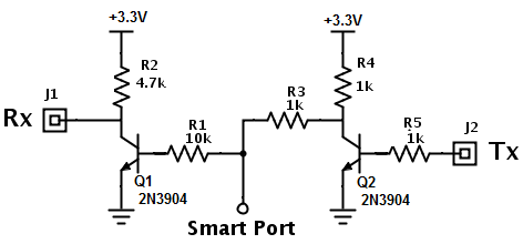
To use UART1 as SBUS invert is required invert SBUS signal.

** BOM List
- 1 x 4.7k ohm resistor
- 1 x 10k ohm resistor
- 1 x 2N3904 NPN transistor
To use UART3 as SPort Telemetry is required invert both RX and TX.
Blink codes for the red LED
- 1 pulse - flash chip
- 2 pulses - MPU6050
- 3 pulses - HMC5883
- 4 pulses - MS5611
- 5 pulses - gyro I2C bus locked
- 6 pulses - mag/baro I2C bus locked
Currently UART4, UART5 and ADC are not implemented.
External SPI flash is disabled in default build.
SBUS input in UART1 require external sbus inverter.
UART1 is RX only
FrSky Hub Sensor in any uart required external single inverter.
FrSky Smart port work only in uart 2 and 3 and require dual inverter.
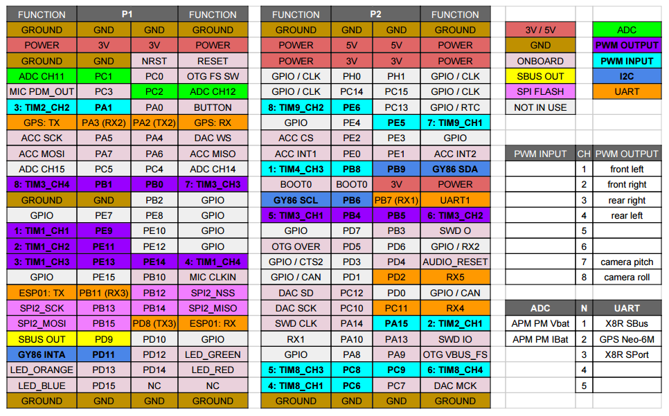
- X8R SBus required one single channel inverter
- X8R Sport required dual channel inverter
- D8R-II-Plus required one single channel inverter
- ADC max voltage is 3.3V, APM PM output 3.3V @ 60A