Repository navigation
Theory Camera and Projection
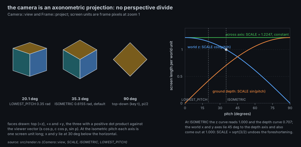
isotop's camera has no perspective. Every world point goes through one affine map, a rotation about the vertical axis, a tilt, a uniform scale and a translation, and nothing is ever divided by distance. The result is an axonometric view, isometric by default, in which parallel lines stay parallel, a body is the same size near and far, and the depth that decides who covers whom is a plain linear function of the world coordinates. This page derives that map from the code, shows why the constant SCALE is the square root of 3/2, derives its inverse (which is what panning and zooming need), and then covers the layer above it: how the camera eases towards a goal, how it fits a view into the frame, and how the tour steers it.
- Perspective first. The geometric construction of linear perspective is credited to Filippo Brunelleschi in Florence in the early fifteenth century and was written down by Leon Battista Alberti in De pictura (1435); the dates of Brunelleschi's own demonstrations are reconstructed from later accounts and disputed in detail. Everything in this page is its opposite: a projection with the vanishing point sent to infinity.
- Orthographic. Gaspard Monge's Geometrie descriptive (published 1799, from lectures given in the 1790s) systematised drawing solids by orthogonal projection onto planes, a method commonly reported to have been treated as a military secret at first (unverified here).
-
Isometric. The word and the rules for isometric drawing are generally credited to William Farish, Jacksonian Professor at Cambridge, in "On Isometrical Perspective" (1822, in the Transactions of the Cambridge Philosophical Society; one source gives 1820 for the reading of the paper). His aim was working drawings from which every dimension could be scaled directly, without the distortion of perspective. The Greek roots mean equal measure: all three axes shrink by the same factor,
$\sqrt{2/3}$ . -
The same number elsewhere. The elevation
$\arcsin(1/\sqrt3) = 35.264^\circ$ is the complement of$\arccos(1/\sqrt3) = 54.736^\circ$ , the angle between a cube's body diagonal and an edge. In solid-state nuclear magnetic resonance that angle is called the magic angle, and samples are spun at it. - Screens. Parallel projection is cheap to compute (no divide per vertex) and keeps sizes comparable, which suits tile maps and technical views. Isometric views became a staple of games on low-power machines; Sega's Zaxxon (1982) is commonly cited as an early arcade example (unverified here). Roads, tiles and sprites on a 2:1 pixel grid approximate the true angle with a slope of 26.57 degrees rather than 30.
- isotop's choice is the old one with a new justification: a process picture whose bodies must be comparable across the screen should not make nearer ones larger. The camera is a mirror image of a right-handed world (see below), which Farish, drawing machines that exist, would have regarded as a defect and which this project has declined to fix.
A parallel projection maps points to an image plane along a fixed direction; it is orthographic when that direction is perpendicular to the plane, which is the case here because depth is just the third coordinate of a rotation. An axonometric projection is an orthographic one whose image plane is oblique to the coordinate axes, so all three axes show; it is isometric when the three axes are foreshortened equally.
Take a unit viewing vector ISOMETRIC. A uniform scale of SCALE) then restores each axis to length 1.
Because there is no perspective divide, the homogeneous coordinate
pub struct Camera {
    center: [f32; 2],   // ground point at the view centre
    zoom: f32,          // pixels per screen unit, default 5.0, clamped to 0.3..65
    rotation: f32,      // turn about the vertical axis, default 0
    pitch: f32,         // elevation above the ground: default ISOMETRIC, 0.35 ..= pi/2
    globe_turn, globe_tilt, globe_held   // Globe only
}
Constants (render.rs): SCALE = 1.224745, ISOMETRIC = 0.615480, LOWEST_PITCH = 0.35 (20.05 degrees: the camera never looks from below the ground), ORIGIN_Y = 0.57. Write Camera::view computes
and Frame::project turns that into frame pixels, with the view centred horizontally and ORIGIN_Y of the way down the frame (the centre sits a little below the middle so buildings have headroom):
As one matrix acting on
\begin{pmatrix} \kappa c & -\kappa s & 0\ \kappa s\sin\varphi & \kappa c\sin\varphi & -\kappa\cos\varphi\ s\cos\varphi & c\cos\varphi & \sin\varphi \end{pmatrix} \begin{pmatrix}\Delta x\ \Delta y\ z\end{pmatrix}, \qquad \kappa = \text{zoom}\cdot\text{SCALE}. $$
Properties, each checkable by hand (and checked numerically while writing this page):
- The three rows, divided by
$\kappa$ for the first two, are mutually orthogonal unit vectors, and the determinant of that rotation is$+1$ . So the map is a rigid rotation into (right, down, towards-viewer) coordinates followed by a uniform scale of the image plane by$\kappa$ and no scale of depth. Depth is therefore measured in world units and is the same whatever the zoom:Item::Sphere'sdepthfield is a world radius for this reason. - The third row is the viewer vector
$V = (s\cos\varphi,; c\cos\varphi,; \sin\varphi)$ thatCamera::viewerreturns, and$D = (p - \text{centre})\cdot V$ . Larger$D$ is nearer, which is why the rasterizers keep the fragment with the larger depth. - At rotation 0 and
$\varphi = \text{ISOMETRIC}$ ,$s = c = 1/\sqrt2$ ,$\sin\varphi = 1/\sqrt3$ ,$\cos\varphi = \sqrt{2/3}$ , so the world axes land at$x \mapsto (\tfrac{\sqrt3}{2}, \tfrac12)$ ,$y \mapsto (-\tfrac{\sqrt3}{2}, \tfrac12)$ ,$z \mapsto (0, -1)$ screen units (down is positive$Y$ ): all of length one, the ground axes at 30 degrees below the horizontal, and every axis with depth component$1/\sqrt3$ . A unit test (default_camera_is_isometric_and_ground_inverts_the_projection) asserts the first two numbers. -
Handedness. The screen triple (right, down, towards the viewer) is left-handed, and the map has determinant
$+1$ , so the displayed world$(x, y, z\text{ up})$ is a left-handed set. Read as a right-handed physical frame, the picture is the mirror image of what a real camera would see. This is derived, not documented in the source; it matters for any view that draws a real-world orientation.
The vertical screen length of the world LOWEST_PITCH (t) heights vanish and the ground is seen at SCALE both ways, which is why the cube in the figure becomes a diamond.
Pointing and panning need the other direction, for points on the ground plane Camera::ground(dx, dy) takes a screen offset in frame pixels from the view centre and returns the ground offset that appears there:
(The rotation here is the transpose of the one in view, since it is its inverse.) It divides by LOWEST_PITCH is positive. A ground area
-
Panning
pan(dx, dy)addsground(dx, dy)to the centre, so a drag of$n$ pixels moves the content by$n$ pixels whatever the pitch and rotation. Keys pan by0.04 * widthpixels, wheel scrolls by0.04 * height. -
Zooming at a point
scale_at(f, dx, dy)keeps the ground point under the screen offset fixed. That point is$P = c + G/\text{zoom}$ with$G$ the zoom-free part ofground; after multiplying the zoom by$f$ it would move to$c + G/(f,\text{zoom})$ , so the centre is shifted by$\frac{G}{\text{zoom}}(1 - 1/f)$ , which is exactlybefore - afterin the code. Ctrl and the wheel use$f = 1.1^{-(x+y)}$ about the pointer, measured from the point(W/2, ORIGIN_Y H)where the centre projects.+/-use 1.15 about the centre. -
look_at(p)centres on a raised point rather than the ground below it. The point appears above its ground point byz / tan(pitch)along the view direction, so the centre is moved to$p_{xy} - \frac{z}{\tan\varphi}(s, c)$ . Setting the vertical image coordinate to zero:$\text{along},\sin\varphi = z\cos\varphi$ and$\text{across} = 0$ . -
front(p, d)is the ground point$d$ world units from$p$ towards the viewer,$p + d,(s, c)$ : the lowest point on screen of a disc around$p$ , used to place labels under a system.
App holds two cameras, goal and camera. Keys, Home, r, search, focus, the tour and the fit change the goal; direct mouse gestures (drag, wheel) change both at once and therefore apply immediately. Each frame the loop runs
camera.approach(&goal, smoothing(elapsed, 0.2))
with approach moving each parameter a fraction
| Input | Effect on the goal (or both cameras) |
|---|---|
arrows, w a s d
|
pan by 0.04 * width px |
+ / =, -
|
zoom by 1.15, 1/1.15 |
e, Q
|
rotation |
| PgUp, PgDn |
tilt(+0.12), tilt(-0.12), clamped to LOWEST_PITCH ..= pi/2
|
t |
pitch to pi/2 if currently at most 1.2 rad, else back to ISOMETRIC
|
Home |
refit (fit = true) |
r |
goal reset to Camera::default() (plus the row's pitch), refit |
| left drag (immediate) | pan(-dx, -dy) |
| other drag (immediate) | rotation |
| Ctrl + wheel (immediate) | zoom about the pointer, factor |
| Alt + wheel (immediate) | rotation |
| wheel | pan by 0.04 * height px; on the Globe, turn and tilt the earth instead |
Zoom is clamped to Camera::scale).
Scene::fit(camera, W, H) frames what the last frame drew. It projects the ground positions (or, if the view gave stage.bounds, those world points) with a probe camera at zoom 1 and centre 0, finds the extent probe.ground(mid_u, mid_v), the ground point whose projection is the middle of the box.
For explicit bounds the centre is also lifted by stage.bounds envelope so the fit does not chase the simulation. While the camera "still frames the whole view" (App::framed) and no tour runs, a sample refits views whose bounds grow with data. The first frame snaps the camera to the fitted goal instead of easing there (App::snap).
The idle tour starts after --tour seconds without input (default 20; 0 disables; any key or mouse event cancels it), or at once on g. It visits targets[index % len] for TOUR_STEP = 6 s each, or until a target no longer has a place. Targets interleave, for Stage::tour, or Orbit's system stars), the busiest process by CPU and the largest by memory, without repeats, so at most 18 targets. A visit clears the selection and sets the goal zoom to fit_zoom * 2.2; every frame the goal centre is set to the target's ground position, and in a view whose row declares face (the Globe, Cortex, Murmuration and Arbor do) the camera is turned to the row's face function's rotation and pitch (the Globe turns the earth to put the target on the near side; Murmuration and Arbor keep the camera as it is) and look_at centres the point itself, since the target floats above the ground. Elsewhere the tour only pans and zooms. A row with tour: false ends any tour on entry.
gpu.rs and shaders.wgsl take frame pixels, not world points, so the camera never reaches the GPU. The vertex stage maps pixel
and the depth by the affine normalisation described in Theory GPU and Parity. There is nothing to divide.
- Size means nothing about distance. Two equal bodies at different depths draw at the same size; only occlusion and the vertical position on screen say which is nearer. A body that rises in the frame is further along the view direction on the ground, or higher.
-
Height and depth are entangled at this pitch. On screen a point at height
$z$ and a point displaced along the view direction by$z/\tan\varphi$ coincide. This is the ambiguity every isometric picture has; the ground grid City draws, and the top-down toggle (t), are the ways out. -
Rotation has two speeds.
eandQturn by a quarter turn,$\pi/2$ , at once (eased); free rotation is Alt-wheel or a drag with a button other than the left.
| What | Where |
|---|---|
Camera, view, ground, pan, scale, scale_at, tilt, viewer, look_at, front, approach, hold, release, SCALE, ISOMETRIC, LOWEST_PITCH, ORIGIN_Y
|
src/render.rs |
Frame::project, Frame::locate, Scene::fit
|
src/render.rs |
Goal and camera, key and mouse handling, the tour, TOUR_STEP
|
src/app/camera.rs: CameraController, App::face; src/app/input.rs: App::command; src/app/pointer.rs: pointer_event; src/app/tour.rs: update_tour, visit, TOUR_STEP
|
smoothing |
src/simulation.rs |
| Clip-space mapping |
src/shaders.wgsl: clip, normalized
|
Figure: docs/figures/theory-isometric-axes.py.
- J. D. Foley, A. van Dam, S. K. Feiner and J. F. Hughes, Computer Graphics: Principles and Practice, 2nd ed., Addison-Wesley, 1990 (parallel projections, orthographic and axonometric views).
- T. Akenine-Moller, E. Haines and N. Hoffman, Real-Time Rendering, 4th ed., CRC Press, 2018 (orthographic projection, and the depth buffer under it).