Repository navigation
Theory Rasterization
The CPU rasterizer is Frame::rasterize: a few hundred lines of straightforward scan-conversion that turn a display list into three images, colour, depth and a pick buffer, one pixel at a time, on one thread. It is the reference implementation: the golden hashes of the test suite are taken from it, and the GPU path is built to reproduce it. This page derives the edge-function arithmetic it uses, states exactly which sampling convention each primitive follows (they are not all the same), accounts for what a frame costs and why, and says what the rasterizer deliberately does not do: anti-aliasing, perspective correction, early depth rejection and parallelism. The last of these is the subject of issue #85 and is context here, not code.
-
Barycentric coordinates. The weights
$\lambda_a, \lambda_b, \lambda_c$ below are August Ferdinand Moebius's barycentric coordinates, introduced in Der barycentrische Calcul (1827): the masses one would place at the vertices so that the point is their centre of gravity. -
Lines first. Early raster hardware drew lines before triangles. J. E. Bresenham's algorithm, "Algorithm for Computer Control of a Digital Plotter", IBM Systems Journal 4(1), 1965, 25-30, steps along the major axis with integer arithmetic only. By his own later account it was in production use by 1962 (he presented it at the 1963 ACM national convention), so the 1965 date is the date of the paper, not of the idea. The simpler digital differential analyser that isotop's
segmentandrayuse accumulates in floating point instead. - Hidden surfaces. Through the early 1970s the usual answer was to sort (see the painter's algorithm in Theory Scene and Display List). The depth buffer, which resolves visibility one pixel at a time and needs no sorting, was described in 1974 by Edwin Catmull in his Utah doctoral thesis, and independently the same year by Wolfgang Strasser in his dissertation at the Technische Universitaet Berlin. Its cost at the time was memory: a word per pixel.
- Edge functions. Juan Pineda, "A Parallel Algorithm for Polygon Rasterization" (SIGGRAPH 1988), showed that coverage can be decided at every pixel in a block by evaluating three affine functions, which is the form that hardware, and this page, use. It replaced scan-line walking as the basis of parallel rasterizers.
- Fill rules and the pixel centre. Graphics APIs later fixed conventions (pixel centres at half-integers and a top-left rule for shared edges) so that two triangles sharing an edge draw each pixel exactly once. isotop's CPU path takes the half-integer centre for triangles and the integer lattice point for spheres, and states the difference below rather than hiding it.
- The plotter drew one line at a time, last. The nearest thing in isotop is the tour's callout pointer, the only stroke drawn after everything else has been rasterized (
stroke, below), and it too is drawn with no regard for what is behind it.
A triangle with screen vertices
which is affine in
Two properties matter for cost. First,
Perspective correctness. Interpolating an attribute linearly in screen space is wrong for a perspective projection, where the correct interpolant is linear in
Fill rule. Pixels whose sample point lies exactly on an edge shared by two triangles can be claimed by both, by neither, or by exactly one, depending on the convention. Hardware uses a tie-break such as top-left so that every such pixel is drawn once. isotop's CPU rasterizer uses none: the test is >= 0 on all three coordinates.
In order:
- Size the buffers:
pixelsto$3WH$ bytes,depthto$WH$ f32set to$-\infty$ ,picksto$WH$ u32set toNONE. Together 11 bytes per pixel, 22.8 MB at 1920 by 1080 (6.2 MB colour, 8.3 MB depth, 8.3 MB picks). The allocations are recycled from the previous frame (Buffers). -
paint_sky: every pixel gets the backdrop colour plus haze (see Theory Scene and Display List). Per column$p(x/W, 0)$ is computed once, per row$p(y/H, 1.9)$ once; when the haze is non-zero (Sky::hazy: any haze channel above 0.5) each pixel costs a multiply-add and a clamp per channel, and otherwise a row is a plain fill. - Take the item list out of the frame and walk it in order, dispatching each
Itemtotriangle,segment,ball,halo,puff,ray,pixel(stars),glyph,splatorfield_triangle(anItem::Field, inrender/field.rs), then put the list back.
There is no tiling, no binning, no sorting and no culling beyond clamping loops to the frame. Painter's order plus a depth test decides everything.
The primitives do not share one convention, and the difference is visible at the half-pixel scale:
| Primitive | Sample point of pixel |
Coverage rule |
|---|---|---|
Triangle |
||
Sphere (ball), Pick (splat) |
|
|
Glow (halo), Puff (puff) |
distance |
|
Line (segment), Beam (ray), Star
|
pixel |
one pixel per major-axis step |
Glyph |
origin truncated to an integer | each set font bit fills a scale by scale block |
Sampling a sphere at the integer point means that a body centred at floor(position.xy) for balls and splats, the raw pixel centre for glows) so that the two rasterizers agree. A consequence of integer-lattice sampling is that the number of pixels a sphere covers is the Gauss circle count
area = E(a, b, c);  if |area| < 0.001 { return }          // degenerate
bbox = [floor(min x), ceil(max x)] x [floor(min y), ceil(max y)], clamped to the frame
for y in bbox.y, x in bbox.x:
    w0 = E(b, c, (x+.5, y+.5)) / area
    w1 = E(c, a, (x+.5, y+.5)) / area
    w2 = 1 - w0 - w1
    if w0 >= 0 && w1 >= 0 && w2 >= 0:
        pixel(x, y, w0*a.z + w1*b.z + w2*c.z, color, pick)
Details worth knowing: both windings draw (no back-face culling); the third coordinate is derived as
if depth < depth_buffer[i] { return }       // pass when depth >= stored
depth_buffer[i] = depth;  picks[i] = pick;  pixels[i] = color
Larger depth is nearer. Ties pass, so the later item wins them. There is no early rejection: a triangle behind a wall still pays for the edge functions of every pixel in its box before the depth test discards the covered ones.
-
ballscans the box$[c \mp \text{outer}]$ with outer$= r + 3$ if selected else$r + 1$ . Per pixel: two divisions ($n_x$ ,$n_y$ by$r$ ),$d = n_x^2 + n_y^2$ ; inside, one square root, the light,tint, andpixel(..., c_z + n_z R, ...). The derivation is in Theory Scene and Display List. Cost:$(2,\text{outer} + 1)^2$ pixel visits. -
splat(anItem::Pick) isballwithout colour or depth writes: where$d \le 1$ and the disc's depth is at least the stored depth, onlypicks[i]is written. -
haloandpuffshare one scan (disc), differing only in the blend (blendtruncates,blend_roundedrounds to nearest). It scans$[\lfloor p - R\rfloor, \lceil p + R\rceil]^2$ , not clamped to the frame (the blend bounds-checks), computing ahypotper pixel and blending where$d < 1$ . Cost$\approx (2R+2)^2$ visits for$\pi R^2$ blends, so the square of the radius. -
segment(aLine):steps = ceil(max(|dx|, |dy|)); for$i = 0..=\text{steps}$ it takes$t = i/\max(\text{steps}, 1)$ and a pixel attrunc(a + (b - a) t), depth interpolated plusLINE_DEPTH_BIAS = 0.02, pickNONE. A digital differential analyser: one pixel per step of the major axis, both endpoints included, no width, no sub-pixel placement. -
ray(aBeam) is the same walk, capped at 8000 steps, blending instead of overwriting and touching neither depth nor picks.strokeandcircle, the tour's annotation, are the same with three pixels per step and a 4000-step cap, applied after rasterization.
Write
where
- Fill dominates, since each term scales with screen area at fixed world content: halving the width quarters the first term and, for bodies sized in world units, quarters the sphere and glow terms too. At 480 by 270 the same scenes take 4 to 12 ms where 1080p takes 25 to 80 (issue #85).
-
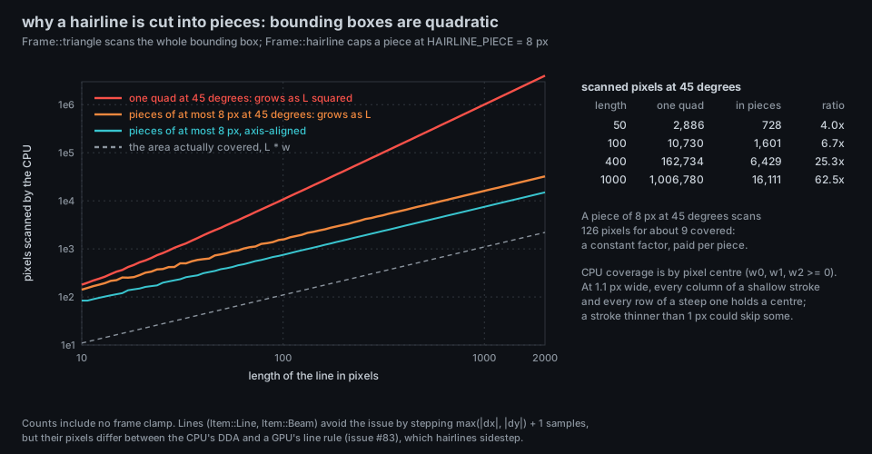
Thin diagonal geometry is quadratic in length unless it is cut: a line drawn as a quad has a bounding box of area
$\sim \ell^2/2$ at 45 degrees against a covered area of$\ell w$ .Frame::hairlinecuts it into pieces of at most 8 px, which makes the cost linear (figure: at 45 degrees a 1000 px stroke scans about 1.0 million pixels as one quad and about 16 thousand in pieces, 62 times fewer, for 1100 covered).docs/VIEW_CONVENTIONS.mdrecords the rule ("a triangle scans its whole bounding box, so split long thin geometry") along with the glow rule and the fact that the sky is painted per pixel. - Overdraw is paid in full. There is no hierarchical depth, no front-to-back ordering and no early-out, so a dense view costs the sum of its parts' pixel footprints, visible or not.
Measured here. One run on this wiki's build machine, a shared 4-vCPU Xeon VM at about 2.8 GHz under unrelated load, so treat the numbers as indicative: --demo --renderer cpu --benchmark 20, 192 processes, minimum of six runs, milliseconds per frame including recording and rasterization, excluding terminal transport.
| View | 480 x 270 | 1920 x 1080 | Ratio (pixels: 16) | Slope between the two, ms per Mpx |
|---|---|---|---|---|
| city | 3.4 | 42.3 | 12.4 | 20.0 |
| orbit | 3.0 | 22.0 | 7.4 | 9.8 |
| ripple | 11.3 | 57.3 | 5.1 | 23.7 |
| flow | 9.2 | 29.3 | 3.2 | 10.3 |
| cores | 4.4 | 39.3 | 8.9 | 17.9 |
Every ratio is below 16: each view has a fixed part (recording and simulating, which does not depend on resolution) and a part proportional to pixels, and the second is 10 to 24 ms per megapixel, 10 to 24 ns per pixel of the frame. The intermediate widths I measured (720, 960 and 1440) were not monotone enough on this machine to quote. Issue #85 reports 50.9, 25.2, 58.8, 44.4 ms for City, Orbit, Ripple and Flow at 1080p on another 4-core machine, the same order. The performance budget in docs/VIEW_CONVENTIONS.md is 10 fps at 1080p with 192 processes and 5 fps at 1000 processes.
Frame::rasterize is single-threaded: render.rs contains no thread, scope or channel. Issue #85 (A26, open) proposes row-banded parallelism with std::thread::scope: split the frame into horizontal bands, one per core, each band rasterizing the whole item list clipped to its rows. The argument that the output would be bit-identical is short and worth stating: a pixel's final value is a function of the sequence of items that cover it, taken in list order, and each band owns a disjoint set of pixels and walks the list in the same order, so every pixel sees the same sequence as before. Blends read only the same pixel, depth and picks are per pixel, so nothing crosses a band boundary. The same issue proposes evaluating edge functions in fixed-point integers (exact, and a clean route to a top-left fill rule), hoisting hypot only where bit-identical. Exactness is the constraint, because the golden test hashes colour, pick and depth buffers.
- No anti-aliasing. Every edge is a staircase. Sphere silhouettes are lattice discs (counts above), triangle edges are pixel-centre decisions, lines are one pixel per major-axis step. Issue #83 lists anti-aliasing as out of scope. How a terminal rescales a 1920-wide image into its cells is the terminal's business (Theory Terminal Graphics).
-
Depth is exact within a primitive and approximate between them. Triangle depth is the exact linear interpolant; sphere depth is exact for a sphere of world radius
$R$ ; a line's depth gets a 0.02-unit bias so that it wins against the surface it lies on. A fragment that loses a depth tie by less than a rounding error is a one-pixel flicker, not a bug. - What the picture hides: the order of translucent items (list order decides), and the half-pixel offsets between primitive families.
| What | Where |
|---|---|
Frame::rasterize, paint_sky, pixel, triangle, segment, ball, splat, halo, puff, disc, ray, glyph, stroke, circle, hairline
|
src/render.rs |
Frame::field_triangle (the span rasterizer of Item::Field) |
src/render/field.rs |
| Constants used by the shaded sphere, ring and line bias | src/render/shared.rs |
| Golden hashes of pixels, picks and depth |
tests/golden.txt, every_view_matches_its_golden_hash in src/headless.rs
|
| Benchmark |
isotop --demo --renderer cpu --benchmark N (src/headless.rs: benchmark, which times recording and rasterizing apart) |
Figure: docs/figures/theory-hairline-cost.py counts bounding-box pixels exactly as the CPU loop would, for a fixed sub-pixel start.
- J. Pineda, "A Parallel Algorithm for Polygon Rasterization", Computer Graphics 22(4) (SIGGRAPH 1988), 17-20.
- T. Akenine-Moller, E. Haines and N. Hoffman, Real-Time Rendering, 4th ed., CRC Press, 2018 (rasterization, fill rules, perspective-correct interpolation).
- J. D. Foley, A. van Dam, S. K. Feiner and J. F. Hughes, Computer Graphics: Principles and Practice, 2nd ed., Addison-Wesley, 1990 (scan conversion, the digital differential analyser).
- isotop issues #83 (known CPU/GPU divergences) and #85 (CPU throughput).