Repository navigation
Theory Scene and Display List
The renderer does not draw a scene; it records one. A frame is a short program, a Vec<Item> of screen-space primitives in painter's order, that either rasterizer can execute and that a test can inspect. This page covers what the primitives are, what a Frame holds, how blending and ordering decide the picture, how a sphere that is only a disc gets a surface and a normal, how a glow falls off, and what the long-lived Scene keeps between frames so that a frame can be a pure function of its inputs.
- The display file. The idea of drawing from a stored list of instructions is older than raster graphics. Ivan Sutherland's Sketchpad (his MIT doctoral thesis, 1963) kept a structured description of the picture and had the display hardware redraw it continuously from that description; the vector displays of the time had to, because a phosphor trace fades.
- Painter's order. Sorting polygons by depth and drawing the far ones first is the painter's algorithm, usually credited to M. E. Newell, R. G. Newell and T. L. Sancha, "A solution to the hidden surface problem", Proceedings of the ACM National Conference, 1972. It fails for cyclic overlap, which is why it was replaced for opaque geometry by the depth buffer (Theory Rasterization); isotop keeps painter's order for exactly the content a depth buffer cannot sort, the blended items below.
- Compositing. Porter and Duff, "Compositing Digital Images" (SIGGRAPH 1984), gave the over operator that the blended items use, and showed why the order of two translucent layers matters.
-
Retained and immediate. OpenGL 1.0 (1992) offered display lists (
glNewList) to record commands once and replay them; they were deprecated in OpenGL 3.0 and are absent from the core profiles that followed, as is the case for OpenGL ES and WebGL, where the application resubmits its geometry each frame. A scene graph (a retained tree of objects that a library traverses to draw) is the other tradition; Strauss and Carey described one in "An Object-Oriented 3D Graphics Toolkit" (SIGGRAPH 1992). isotop's design sits at neither: the retained part is theScene's memory, the drawn part is a flat list rebuilt each frame. - Impostors. Drawing a sphere as a screen-space disc whose depth and normal are computed per pixel, rather than as a tessellated mesh, is known as an impostor or ray-cast sphere; the technique became common in molecular visualisation, with Gumhold, "Splatting Illuminated Ellipsoids with Depth Correction" (VMV 2003) a frequently cited early description (venue and year unverified here).
- The display list of Sketchpad outlived the program that drew it. The display list of isotop lives for one frame, and the 30 bits of a
Glyphthat its 7 by 14 bitmap does not use have so far outlived every one of them.
render::Item is a Copy enum. Every point is already in frame pixels: a world point has been through Frame::project, so the third component of a Point is view depth (larger is nearer), not a pixel.
| Item | Fields | Depth test | Writes colour | Writes depth | Writes pick | Blended |
|---|---|---|---|---|---|---|
Triangle |
three (x, y, depth), Color, pick |
yes, >=
|
yes | yes | yes | no |
Line |
two (x, y, depth), Color
|
yes, >=, depth plus LINE_DEPTH_BIAS
|
yes | yes | writes NONE
|
no |
Sphere |
centre (x, y, depth), pixel radius, world radius depth, Color, pick, selected
|
yes, per pixel, at the sphere's surface depth | yes | yes | yes (the ring too) | no |
Glow |
centre (x, y), radius, Color, strength
|
none | yes | no | no | yes, weight strength (1-d)^2
|
Puff |
centre (x, y), radius, Color, strength
|
none | yes | no | no | yes, weight strength (1-d)^2, strength clamped to 0..1, rounded to nearest on both backends |
Beam |
two (x, y), Color, weight |
none | yes | no | no | yes, constant weight |
Star |
(x, y), Color
|
at BACKGROUND = -10000
|
yes | yes | writes NONE
|
no |
Glyph |
integer origin, integer scale, bits: u128, Color
|
none | yes, overwrites | no | no | no |
Pick |
centre (x, y), radius, depth, pick |
yes, >=, per pixel |
no | no | yes | no |
Field |
three (x, y, depth), three uv, a field index |
yes, >=
|
yes, sampled from the field | yes | yes, the owner of the nearest node | no |
Notes that the table cannot carry:
-
Pickis a disc that writes only the pick buffer, so translucent or splatted content stays clickable. It must be recorded after the geometry it lies over, because it writes no depth and later geometry covers it wherever that geometry passes the depth test. The Murmuration view records them under its splatted flock. See Theory Picking. -
Glyphcarries a 7 by 14 bitmap (glyphs::WIDTHandHEIGHT) as 98 bits of au128, bitrow * 7 + column. Only the Matrix view emits them. Labels, popups and the status lines are not display-list items at all; they are terminal text (Theory Terminal Graphics). -
Puffis aGlowwith the same profile that blends with round-to-nearest on the CPU, as the GPU's blend unit does, so any number of stacked puffs still agree between the backends. It is for content whose look is the density of many splats (Murmuration's flock); a lone halo is aGlow. -
Fieldis a triangle whose colour and pick come from a grid of colours (render/field.rs:Field,Frame::field), sampled bilinearly in node units. It is for grid simulations; the#[expect(dead_code)]on the variant outside tests says no view records one yet. -
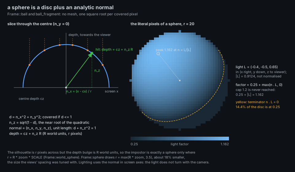
Sphereis an impostor: no mesh, a pixel disc whose depth and shading are computed per pixel from the disc geometry (below). -
Starexists only for theSpacebackdrop and for views that scatter their own (Necropolis). Both rasterizers need stars to be recorded before anything else (see ordering).
Views rarely build Items by hand. The Frame methods project world points and push items:
| Method | Emits |
|---|---|
facet, quad
|
one triangle; two triangles [0,1,2], [0,2,3]
|
line |
a Line (dropped if its extent exceeds 12000 px, to bound CPU work) |
beam |
a Beam, same cut-off |
hairline(camera, a, b, color, width) |
a ribbon of width pixels as pairs of triangles, in pieces of at most HAIRLINE_PIECE = 8 px, pick NONE; rasterizes alike on both back ends (Theory Rasterization shows why it is cut) |
glow |
a Glow at a projected point |
sphere(camera, p, radius, color, pick, selected) |
a Sphere of pixel radius max(radius * zoom, MIN_BODY_PX = 3.5) and depth = radius
|
world_sphere |
a Sphere of pixel radius radius * zoom * SCALE, the exact projected size, pick NONE
|
outline |
two rings of 48 Lines facing the viewer (radius 1.0 and 0.6 times the sphere's, the inner one at 0.45 brightness): a body drawn hollow |
pick_disc |
an Item::Pick
|
thing_pick(thing) |
not an item: returns the pick value for a non-process pickable |
Frame::stroke and Frame::circle are different: they write straight into frame.pixels after rasterization, ignoring depth, and the tour's callout pointer uses them. They work identically on CPU and GPU frames because both leave their pixels in frame.pixels.
pub struct Frame {
    width, height,
    sky: Sky,                // backdrop, haze colour already scaled by strength, time
    items: Vec<Item>,        // the display list
    pixels: Vec<u8>,         // RGB, 3 bytes per pixel
    depth: Vec<f32>,         // CPU rasterizer only; larger is nearer
    picks: Vec<u32>,         // identity index, THING-tagged thing index, or NONE
    identities: Vec<Identity>, // pick value -> process
    things: Vec<Thing>,      // (pick & !THING) -> non-process pickable
    anchor: Option<[f32; 2]> // pixel position of the selected process
}
Frame::new takes the previous frame's allocations (Buffers, via Frame::release) so that steady-state rendering does not page-fault fresh megabytes every frame; Scene::spare carries them. For a Space backdrop it also records clamp(width * height / 1100, 200, 4000) Star items of colour (37, 48, 71) at positions hash::knuth(i) % width and hash::knuth(i).rotate_left(13) % height: at 1920 by 1080 that is 1885 stars. The pick value of a process is its index into identities; of a thing, its index into things with the THING bit (1 << 31) set; NONE is u32::MAX. Details in Theory Picking.
The model is the painter's algorithm with a depth buffer for the opaque primitives and no depth at all for the blended ones. Both rasterizers execute the list front to back in record order, and the rules are:
-
Opaque, depth-tested items (
Triangle,Line,Sphere,Star) pass wheredepth >= stored. A tie therefore goes to the later item. A fragment that passes writes colour, depth and pick together. -
Blended items (
Glow,Beam) never read or write depth or picks. They composite into whatever colour is already in the pixel at the moment they are painted. A glow recorded before a sphere that is nearer is overpainted by it; a glow recorded after is on top of everything, even of things nearer than the glow's centre. View code orders its items on purpose for this reason. -
Glyphoverwrites pixels, with no depth and no blending. -
Pickwrites only the pick buffer, with the opaque depth test.
The blend itself is the standard over operator with the weight as coverage (Porter and Duff 1984), applied per channel to the stored colour d:
Because each blend reads the result of the previous one, the order of two translucent items matters unless their colours agree. For two blends of weights
which vanishes only when
On the CPU the stored channel is a byte and the result is converted with as u8, which truncates. Reading the code gives an asymmetry that is easy to miss: when the target colour is darker than the stored one, any positive weight lowers the channel by at least one level (the result is slightly below the integer and truncates down), while toward a lighter colour a step smaller than one level is lost. A faint beam darkens and does not brighten, on the CPU. The GPU blends in normalised floats and rounds to nearest. This is one of the documented divergences in Theory GPU and Parity.
Two further consequences of the rules:
-
Stars first. A CPU
Staris a depth-tested write atBACKGROUND = -10000; a GPU star is drawn with the compare functionAlwaysand no depth write. They agree only because stars are the first items in the list.Frame::newrecords its own before anything else, and Necropolis records its own first indraw. -
Lines punch holes in picks.
LinewritesNONEinto the pick buffer where it passes, so a one-pixel decoration drawn across a body makes that pixel unclickable. Decorative strokes that must not do this areBeams (which never touch picks) or sit behind the body in depth.
A body is drawn as a disc of pixel radius
covers the pixel if
Why this is a ray-sphere intersection. The camera is orthographic (Theory Camera and Projection), so the ray through a pixel is parallel to the depth axis. A sphere of radius
with
The normal at the hit point is
Lighting is Lambert's cosine law with an ambient floor, in screen axes (render::shared:
(tint, on the CPU; floor(color * 255 * light) clamped, in the shader.) Three things follow from the numbers, and the first two are not stated in the code:
- The light vector
$L = (-0.4, -0.5, 0.65)$ is not normalised:$|L| = 0.9124$ . The maximum of$n \cdot L$ over unit normals is$|L|$ , reached at$n = L/|L| = (-0.438, -0.548, 0.712)$ , upper left and 0.70 of the radius from the centre. The largest factor any pixel can receive is$0.25 + 0.9124 = 1.1624$ , so the capSPHERE_LIGHT_MAX = 1.2is never active. - About 14.4% of the disc's area has
$n \cdot L \le 0$ and sits at the ambient floor 0.25 (computed by summing over the disc; the terminator in the figure is the great circle$n \cdot L = 0$ , which projects to an ellipse). - The light is fixed in screen space. It does not turn with the camera, and a body looks the same lit whatever the view rotation: it is a billboard with a painted-on light, not a lit solid.
Silhouette versus depth. The depth bulge is SCALE = sqrt(3/2)). Frame::world_sphere draws exactly that. Frame::sphere draws MIN_BODY_PX = 3.5 keeps a tiny process visible and clickable at any zoom.
Selection. A selected sphere scans out to SELECTION_RING_WIDTH), and pixels with SELECTION_COLOR = (237, 220, 154) at the centre depth SPHERE_EDGE) but draws nothing outside
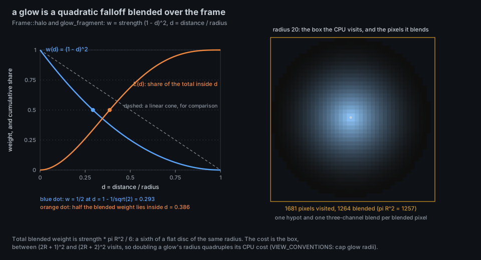
A Glow of radius
The profile is a quadratic that reaches zero with zero slope at the rim, so a halo has no visible edge, unlike a linear cone. The total weight it injects is, in polar coordinates,
a sixth of a flat disc of the same radius. Half of that weight lies inside docs/VIEW_CONVENTIONS.md asks views to cap glow radii and counts.
The sky is not an item. Frame::rasterize paints it first, every pixel, from Sky { backdrop, haze, time }.
| Backdrop | Base colour (0 to 255 units) at screen height fraction |
|---|---|
Dusk |
|
Space |
|
Sea |
|
Void |
|
Twilight |
three stops down the frame: TWILIGHT_TOP TWILIGHT_MIDDLE TWILIGHT_KNEE), then to TWILIGHT_HORIZON |
On top of the base is the pressure haze, a slowly moving smooth density field that carries system pressure into the picture:
with model::bounded, a saturating hyperbola) and
CPU pressure tints the sky warm, memory pressure magenta, I/O pressure blue, and none of them can exceed what saturation allows. A view whose row sets haze: false gets render::shared); the haze strength mapping is computed once on the CPU.
Scene::render takes one RenderInput (snapshot, view, camera, size, selection, thing, time, --limit, focus, paused, toured) and returns a Frame. The scene is long-lived, and it exists to keep what a frame must not recompute. It holds frame-wide state only: what every view and the app share. A view's own memory (its layout, its simulated medium, its history of what it has drawn) lives in its ViewModule, which the scene builds from the registry row (ViewInfo::build) when it is created and owns in modules, one per row in registry order. Every view is a module, City, Orbit, Ripple, Flow, Matrix and Coop included; there is no view the scene draws itself. The doc comment on Scene says so, and a test (scene_has_no_view_specific_fields) stops compiling until a new field is listed in it.
| State | Held for |
|---|---|
resources |
each process's CPU and memory eased towards the samples, |
births, arrivals, newborn
|
the birth-growth animation (growth, in simulation.rs: a cubic ease-out over GROW_SECONDS = 0.9) and the true age of a process that arrived after the first frame (Stage::age) |
previous, deaths, splashes
|
where each process was last drawn, the exit flash (FADE_SECONDS = 1.2) and the disturbances any view's medium may take |
links, highlight
|
the c key's link mode and the processes whose links stand out |
positions, places, titles, bounds, notes, sparklines, tour, popup, callout, headroom
|
the last frame's Stage outputs, which the app reads back |
history |
the shared per-process history (Theory History), filled on every sample whichever view is shown |
rows, modules
|
the registry rows and each view's module, built from its row; record feeds every sample to every module |
clock |
the FrameClock behind Stage::dt
|
spare |
the previous frame's buffers |
The stable placement of the view families (Theory Stable Layout) is therefore not scene state: City, Orbit, Ripple and Flow keep theirs in src/views/city.rs, orbit.rs, ripple.rs and flow.rs (sharing src/views/systems.rs), and the simulated media of Ripple and Flow live in their modules.
One frame does, in order: record the sample into the history; compute dt; ease the processes; select the processes to draw (admitted: the focused subtree or all, in Identity order, cut to --limit with the selection swapped in); build the sky from the pressures and the row's haze flag; make the Frame; clear the per-frame outputs; call the shown view's module (draw_view, which builds a Stage); draw the socket links according to the row's links rule (All, Quiet, which draws only the highlighted processes' links unless c asks for more, or DrawnByView, which draws none); draw the exit flashes where the row has the flash flag; locate the selected process's anchor.
-
Links (
draw_links) are quadratic Bezier arcs lifted above the plane byspan * 0.35, in 20 segments, asBeams (orhairlines when the row setslink_strokes), colour(80, 175, 235)and weightmin(0.1 + 0.05 ln count, 0.3), or(150, 232, 255)at 0.8 for a highlighted process, with a travellingGlowof radius 5. Connections that leave the machine rise as ten fading beams in pink. -
Exit flashes (
flash_exits) draw an expanding ring ofLines (radius$0.6 + 3.4,\text{age}$ world units) and, for the first 35% of the 1.2 s, a glow of radius$\max(2,\text{zoom}, 10)$ and strength$1 - \text{age}/0.35$ .
A view reads Stage and writes back only through it. Inputs: the Frame, the Camera, selected, thing (selected or hovered non-process), toured, focus, links and highlight, limit, time, frames, dt, history, splashes, newborn, and the eased births, arrivals and resources through growth(id), age(id) and eased(process). Outputs:
| Output | Consumed by |
|---|---|
positions (identity to world point) |
picking anchors, labels, the tour, the exit flash, the harness |
bounds (fixed envelope of world points) |
the camera fit, for content that moves by itself |
places (world point and text) |
scene labels |
titles, headroom
|
system labels under their outer edges; how far the content rises above the ground, for the camera fit |
sparklines |
generated braille lines after the notes (cleaned by terminal::clean_sparkline) |
notes, popup
|
extra inspector lines, after the sockets / after the process's own figures |
tour (TourTarget { id, position, weight }) |
the tour, heaviest first |
callout |
extra lines in the tour's callout |
The return value of draw is the number of processes shown; the rest are counted as collapsed.
What the display list makes certain: every pixel of colour traces to an item, and every item to a view's draw (or to the sky, links and flashes the scene adds). What it cannot show: where a glow's source is (it has no depth), whether two overlapping translucent things are in the order they are physically in (the list order is what counts), and true sphere size (sphere draws 18% small and never below 3.5 px). A viewer should read a body's size as monotone in its quantity, not as a metric radius.
| What | Where |
|---|---|
Item, Frame, Buffers, Sky, Backdrop, Frame::sphere, world_sphere, hairline, halo, ball
|
src/render.rs |
Scene, Scene::render, ease, admitted, draw_links, flash_exits, Stage, FrameClock
|
src/render.rs |
ViewModule, ViewInfo, Build, REGISTRY (what the scene builds its modules from) |
src/views.rs |
Field, Frame::field, ShadedField
|
src/render/field.rs |
Shared constants (SPHERE_*, SELECTION_*, LINE_DEPTH_BIAS, sky and haze constants) |
src/render/shared.rs |
The shader's ball_fragment, glow_fragment, sky_fragment
|
src/shaders.wgsl |
Easing helpers (growth, smoothing) |
src/simulation.rs |
Figures: theory-sphere-impostor.py and theory-glow-falloff.py.
- T. Porter and T. Duff, "Compositing Digital Images", Computer Graphics 18(3) (SIGGRAPH 1984), 253-259.
- J. H. Lambert, Photometria, 1760 (the cosine law of illumination).
- J. D. Foley, A. van Dam, S. K. Feiner and J. F. Hughes, Computer Graphics: Principles and Practice, 2nd ed., Addison-Wesley, 1990.
- T. Akenine-Moller, E. Haines and N. Hoffman, Real-Time Rendering, 4th ed., CRC Press, 2018.