Creating your own pcore with nf10_coregen.py tool
There is some ways to create a new pcore and add it to NetFPGA 10G datapath. First of all, its likely starting from some reference project and then:
-
modify an existent pcore, adding your functionality on it;
-
create a set of files and directory structure that will be recognized by Xilinx Platform Studio;
-
use the nf10_coregen.py tool to generate a pcore template where you might add your functionality.
This documentation addresses the third option. You should not assume that this is the main or only way to create a pcore. Also referer to other documentations like Stanford Summer Camp 2013 Slides (section VII) and European Spring Camp 2013 Slides.
This page assumes that you followed the Getting Started Guide, are familiar with Xilinx EDK and source'd the bashrc_addon_NetFPGA_10G file in your settings.
Let's suppose that you what to create a new NIC design called nic_tracer based on Reference NIC which will contain a pcore called packet_tracer placed between the "Output Port Lookup" and "BRAM Output Queues" modules, as illustrated on NetFPGA 10G Reference NIC block diagram.
The process, in a glance, is to copy reference_nic directory, create a pcore with nf10_coregen.py tool and wire up the pcore between nf10_nic_output_port_lookup_v1_10_a and nf10_nic_output_port_lookup_v1_10_a pcores.
So, you should:
# cd $NF_ROOT/contrib-projects
# cp -r ../projects/reference_nic nic_tracer
# cd nic_tracer
# make clean
# $NF_ROOT/tools/scripts/nf10_coregen.py --path hw/pcores --name packet_tracer
[Some info is displayed. Read them :-) ]
Now you should have two files:
# ls hw/pcores/packet_tracer_v1_00_a/hdl/verilog
packet_tracer.v  user_logic.v
The packet_tracer.v is your top module file, which instantiates a "user logic" module and a "ipif_regs" register module.
The "user logic" module behaviour code should be defined within the user_logic.v file.
By default is created one write-only and one read-only registers. You can customize the registers as you wish. See the packet_tracer.v "NUM_RW_REGS", "NUM_RO_REGS" and "NUM_WO_REGS" localparams declarations.
Run xps to instantiate and wire the pcore:
# xps hw/system.xmp
You should see in the "IP Catalog" panel a "Project Local PCores" tree, expanding its "NetFPGA-10G" item a "Packet Tracer" pcore should be available just like highlighted in the following picture:

Then right-click on "Packet Tracer" and choose "Add IP" and click:

An window will show up with buses information. See in the "Component Instance Name" field the instance's name you are creating. You should leave it as suggested. Make sure that "C_M_AXIS_DATA_WIDTH" and "C_S_AXIS_DATA_WIDTH" are 256 bits long and "C_M_AXIS_TUSER_WIDTH" and "C_S_AXIS_TUSER_WIDTH" are 128 bits long. Click "Ok"

Then select the MicroBlaze instance your pcore will be connected to. Should have just one instance, so click "Ok".

An instance of "Packet Tracer" pcore, called by default "packet_tracer_0" should appear at "Bus Interface" tab panel, as highlighted:

Since your pcore has registers, some address must be assigned to them. There's a probability that XPS can't assign such address during instantiation. So, you must click on "Address" Tab and check it out. If you pcore instance is listed on "Unmapped Address", you should click on the small yellow icon on the top right of the panel (Generate Address button). Doing so you should see that your pcore will go up to the "microblaze_0's Address Map" with a address assigned to it.

Now, go back to the "Bus Interfaces" tab and wire the "S_AXIS" bus of your pcore (by click in "No Connection") choosing "nf10_nic_output_port_lookup_0_M_AXIS".

Then expand the "nf10_bram_output_queues_0" instance and connect its "S_AXIS" bus (also by clickin in "No Connection" to "packet_tracer_0_M_AXIS". These two steps wired your pcore between "nf10_output_port_lookup" and "nf10_bram_output_queues". Of course you can place it elsewhere as you need.

As a final step, you must connect the reset and clock signals. Click on the "Ports" tab and expand the pcore signals. A s_axi_aresetn port should appear. Click on the red pencil area:

And select reset_0:

Then select Peripheral_aresetn and click elsewhere.

The selection should be made and the "Connected Port" should appear as reset_0::Peripheral_aresetn:

Expand (BUS_IF) M_AXIS and the s_axi_aclk signal and change the clock from CLKOUT0 to CLKOUT1:
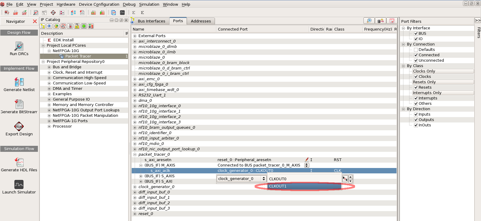
And so, the clock signal for the bus should appear as clock_generator_0::CLKOUT1:

That's it! Now you should close the project and exit XPS. After that you can generate the register include files:
# make -C hw regs
Be aware that the rules in reference_nic's Makefile are hardcoded, so it will produce register related filenames with "reference_nic", like the Python lib/Python/reg_defines_reference_nic.py script. You can change the Makefile then.
The sw/host/reg_defines.h file should be generated with, at least, two C macros that labels the base and high address choosen by XPS above.
# grep -i packet_tracer sw/host/reg_defines.h
An output example:
#define XPAR_PACKET_TRACER_0_BASEADDR 0x7EE00000
#define XPAR_PACKET_TRACER_0_HIGHADDR 0x7EE0FFFF
These addresses might vary. Keep in mind that those C macros are named after the pcore instance ("packet_tracer_0" in this example). Just for being informative, run xps hw/system.xmp again, click the "Addresses" tab and check that both addresses are the same.
Now you can start some tests, simulations and, then, synthesis. Please refer to the mentioned slides and other wiki pages to do so.
Finally, one last thing. The "template" pcore created by nf10_coregen.py is just a "bypass-like" pcore with only a FIFO. So it might be placed at datapath without disrupting it. Then you can add your own logic.